QSat APSS
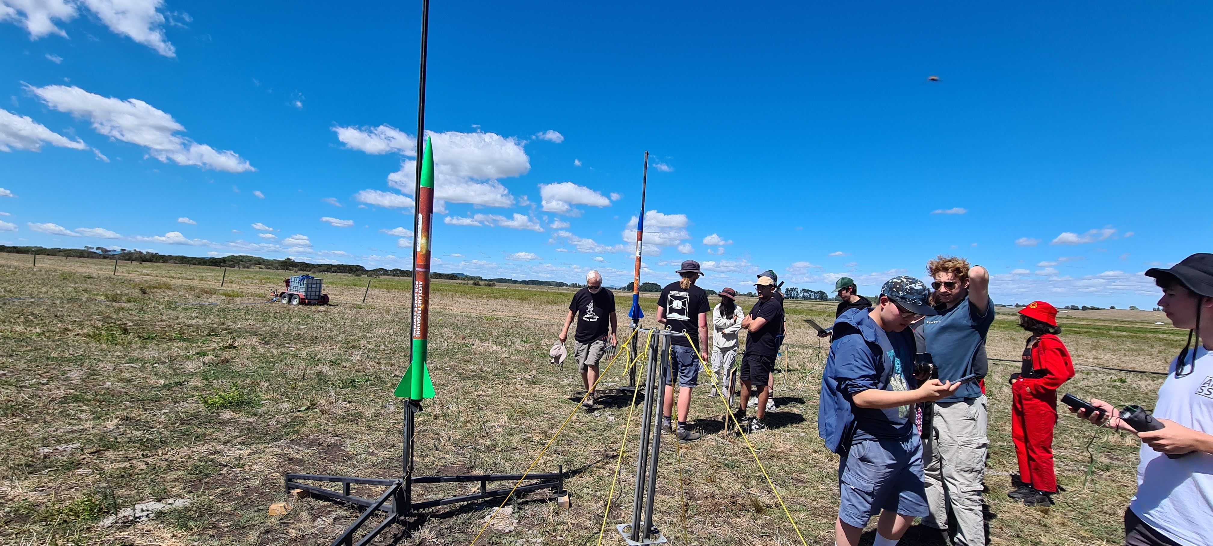
We launched a film camera in a rocket in 2025.
With modern electronics, advanced CAD, and the latest 3D printing technology, we managed to capture an entirely white film frame. This is the cool story of how we managed to capture perhaps the most boring photo possible.

What is PSat?
PSat, or “Pico Satellite”, is a summer program run by the Auckland Program for Space Systems (APSS) at the University of Auckland. The program is designed to give students hands-on experience in building and launching a small “pico-satellite” payload. The payload can be anything the students like, as long as it’s self-contained, and fits into the University’s Sudden Rush I class rockets.
At the start of the program, many teams are formed. Those teams are filtered down through design reviews and checkpoints to a final few teams that get their payload launched at the end of the program. The design reviews are loosely based on a simpler version of NASA’s mission lifecycle.
Every team also had access to reference designs, which were provided by the APSS team. These reference PCB’s were designed to vertically stack, and covered the basic functionality needed for a PSat. The reference designs included a battery powersupply, a MSP430 based MCU board, and a beacon board with a LoRa radio, GPS, and a buzzer.
This year, the teams were provided with the following theme:
Create a superlative PSat.
Your PSat must be the best at something. It can be the fastest, the most powerful, the most efficient, or the most fun.
The concept
To fit the theme, we select “The Most Retro” as our superlative. We decided to build a payload that would take photos upon deployment using a commercial film camera. Alongside the film camera, we wanted to include a small digital camera, and a sensor/communication module to send telemetry data back to the ground.
![]()
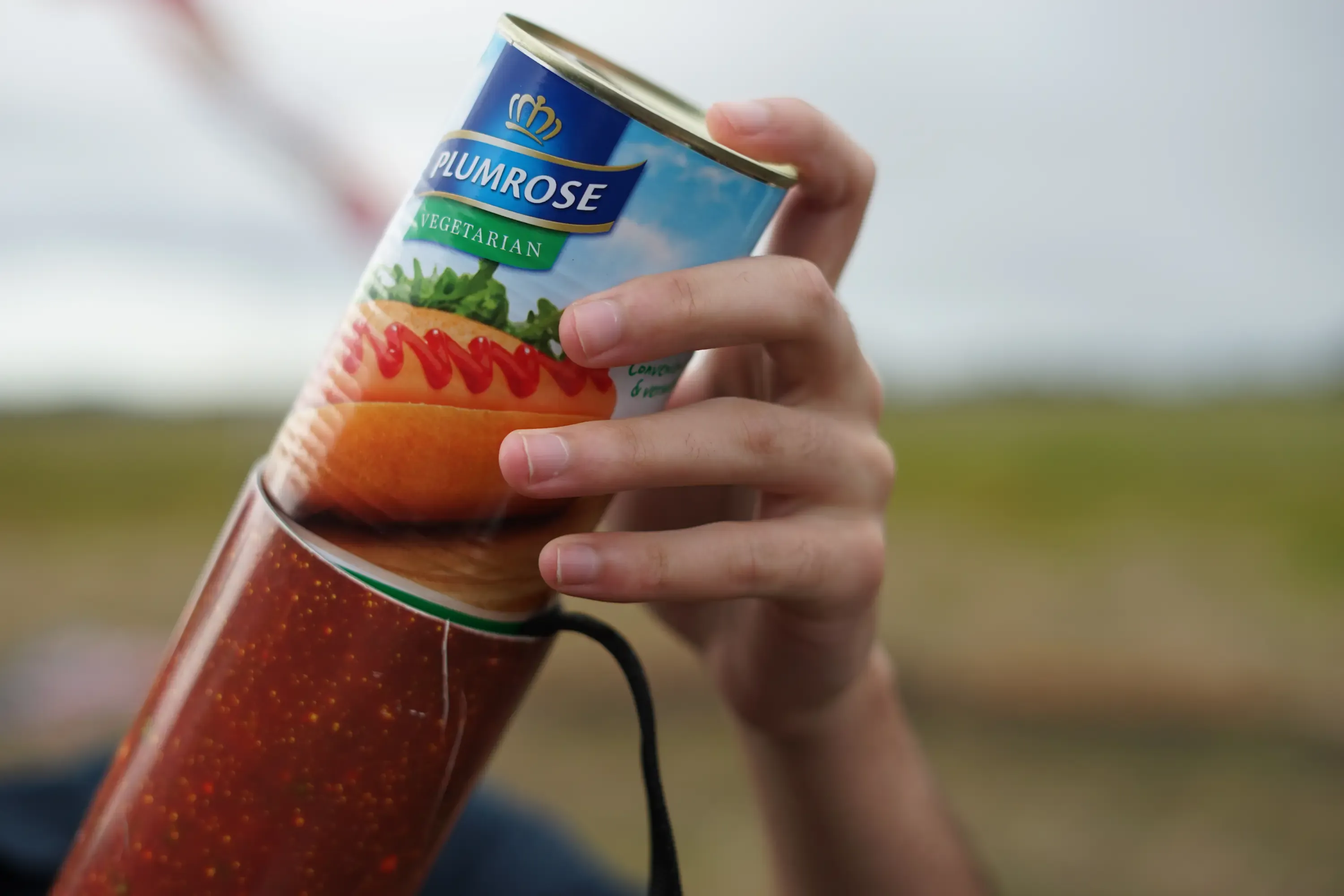
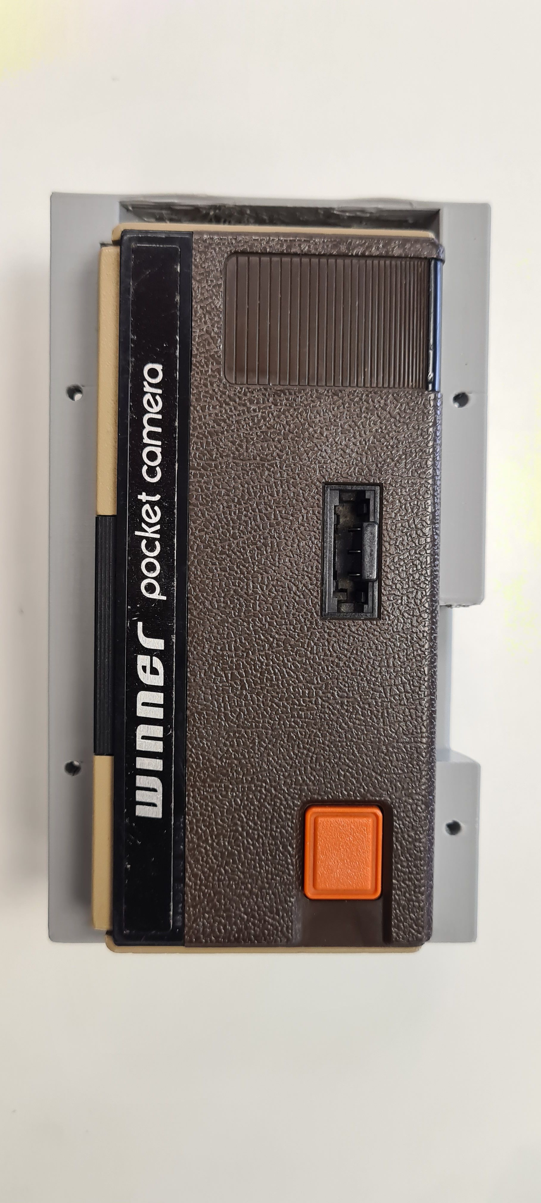
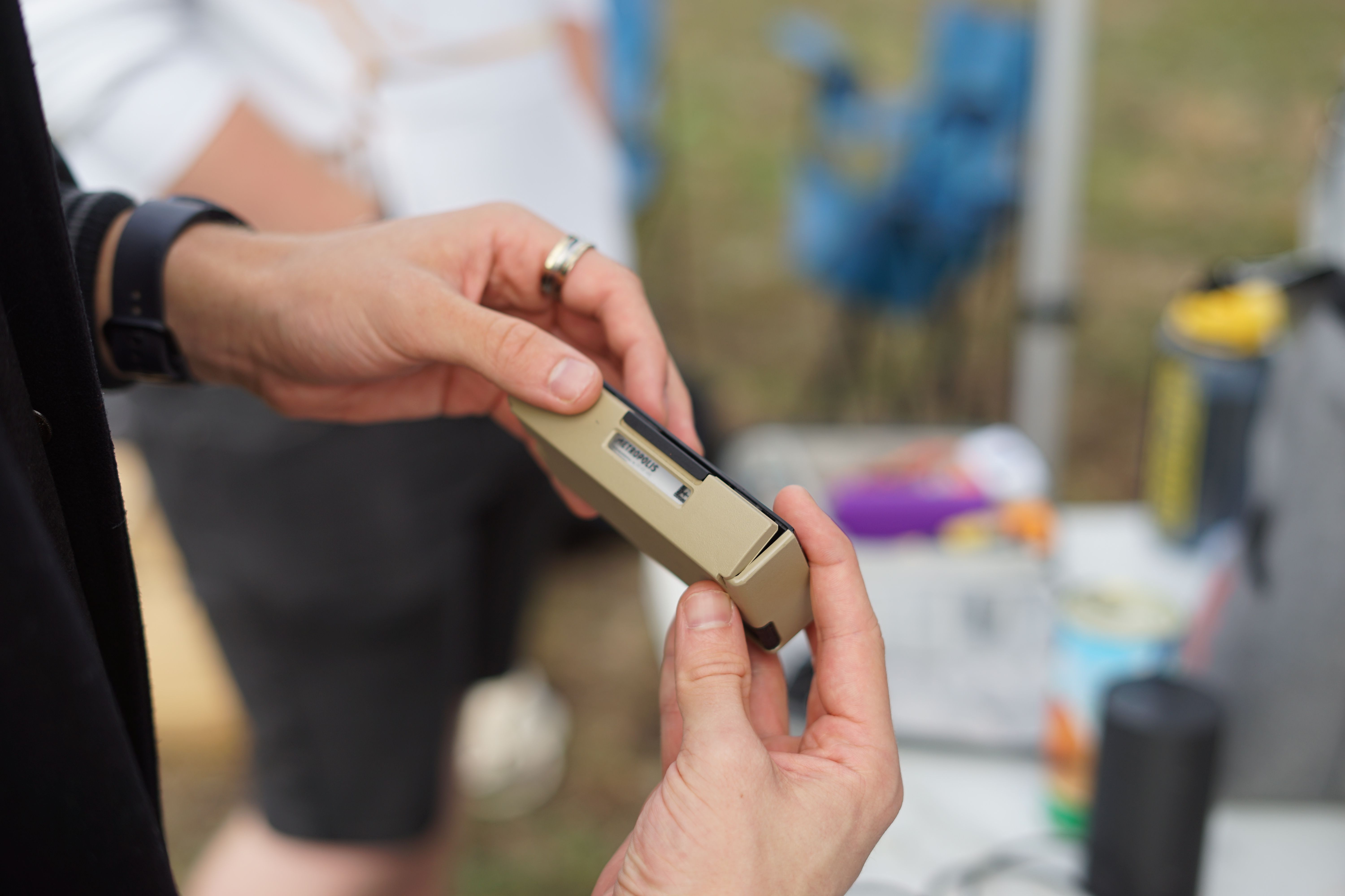
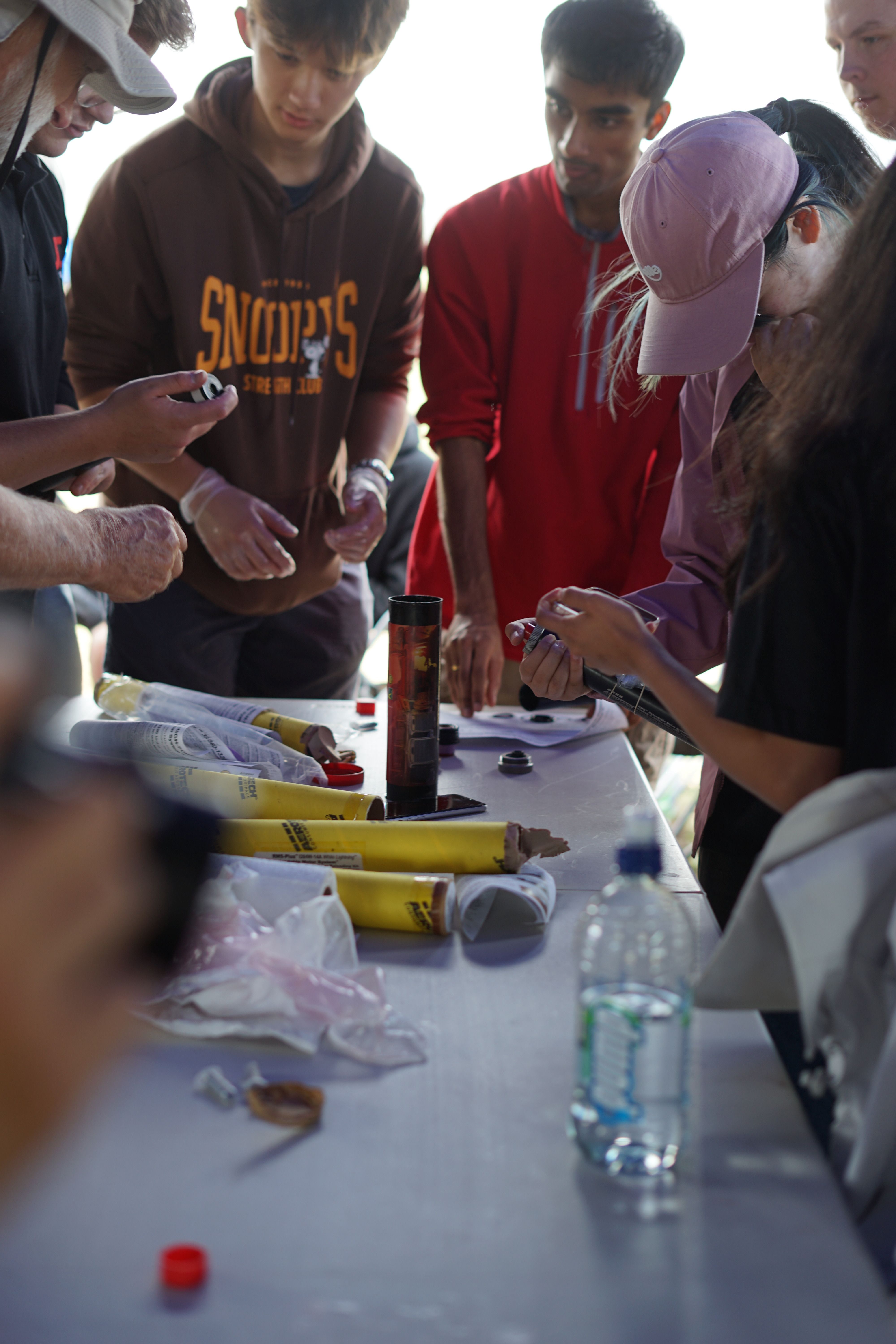
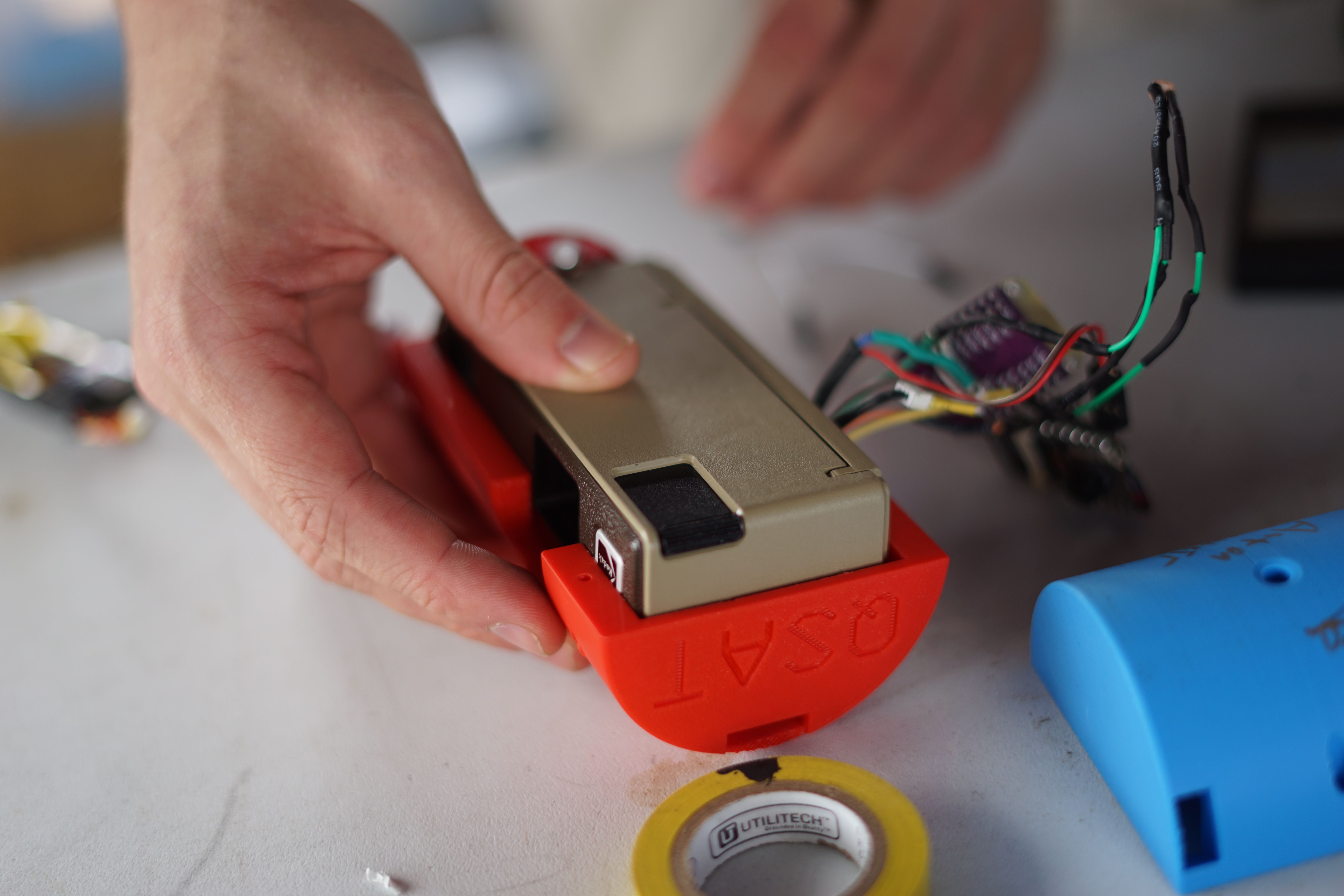
The payload must fit into a tiny space, around the same size as a tin can, so we needed a tiny film camera to match. We settled on the Kodak Winner Pocket Camera, a small 110 film camera that was one of the official sponsors of the 1988 Olympic Games. The camera is small, light, and dead-simple to operate. It has a fixed focus lens, a fixed aperture, and a fixed shutter speed. The only thing we needed to automate was the shutter release and film advance.
Mission Definition Review
Once we had our concept, we needed to present it to the APSS team for approval. It was a simple presentation, where we outlined our concept, the components we would use, and the timeline for the project. We also outlined the risks and challenges we would face, and how we would mitigate them. The presentation was well received, and we were given the green light to proceed with the project.
First iteration
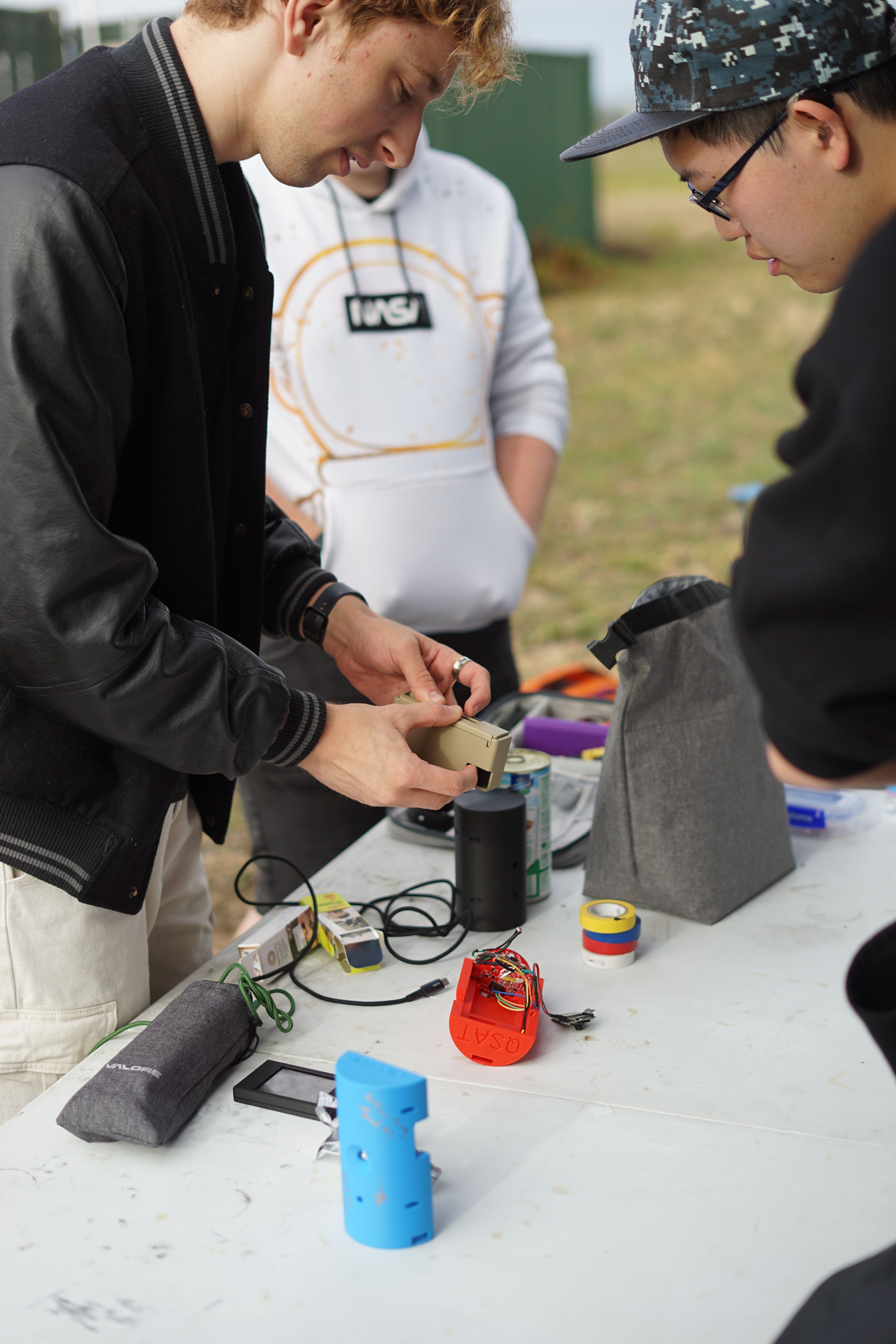
Once we had the green light, we split the team in two and started to design our payload. Both the mechanical team and the electrical team started to work on the first prototype from both ends, working towards the Preliminary Design Review deadline. The mechanical team started to design the payload structure, while the electrical team worked on the main Motherboard. We also started to source the components we would need for the project.
Electrical
Despite the very analog nature of the film camera, we needed a full electrical subsystem to act as our flight computer. Not only did it need to detect and trigger the film camera at apogee; we also aimed to dynamically advance the film frame, trigger a digital camera to capture matching shots, and even broadcast flight information over a LoRa radio. Ambitious plans indeed.

Due to the mechanical constraints below, we had super limited space for the onboard flight system. Unlike most other teams, we couldn’t just design an extension to the example PCB designs, as they were designed to stack, using up our precious vertical space within our PSAT. To make more space for the camera itself, we decided on a long motherboard like design.
Mechanical diagram should go here? Something to show where the Motherboard was inside the PSAT
To start, we merged the MCU & Beacon example PCB’s into one schematic, and began work in Altium. We had a heap of features to integrate.
Motor control system
Unfortunately our film camera was designed for humans to operate, not robots. The trigger was simple to operate, a basic push-button mechanism the fired the fixed shutter. The film advance mechanism, on the other hand, was another beast. To advance each frame, you had to slide the flat lever back and forth until it physically locked in place. Sometimes this required just one slide, other times you needed to work it back and forth three times for a single shot.
While this tactile feedback system works perfectly for a human who can see and feel the mechanism, it posed a significant challenge for our robotic system that had to determine the correct position purely through mechanical feedback.
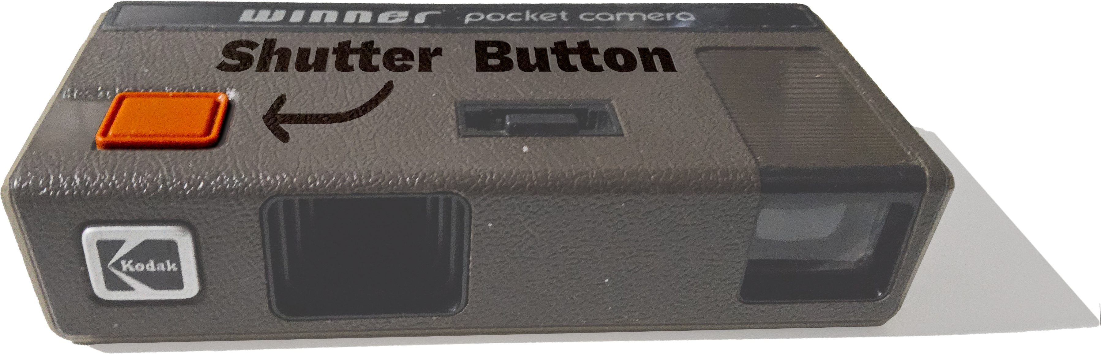
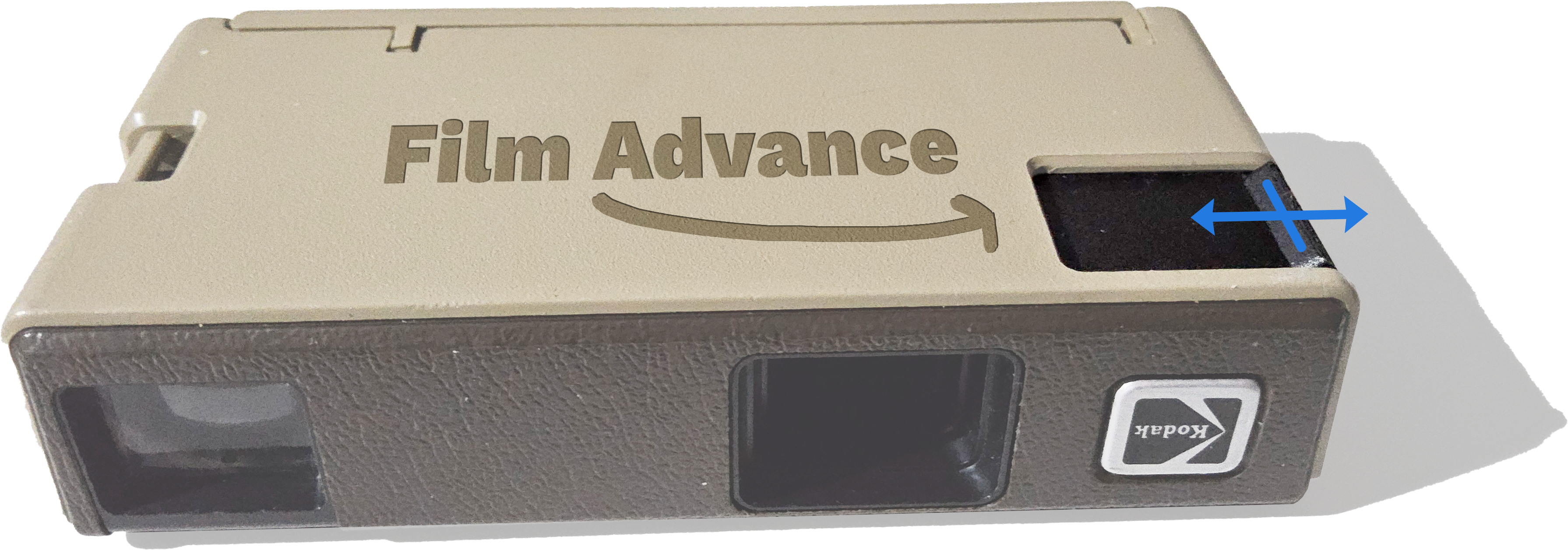
In a bid to keep things as simple as possible, we decide to use a servo for the shutter trigger, and a current sense motor combo for the film advance. The current going through the motor will peak when the motor stalls, we can theoretically find our three jam states from a single sensor.

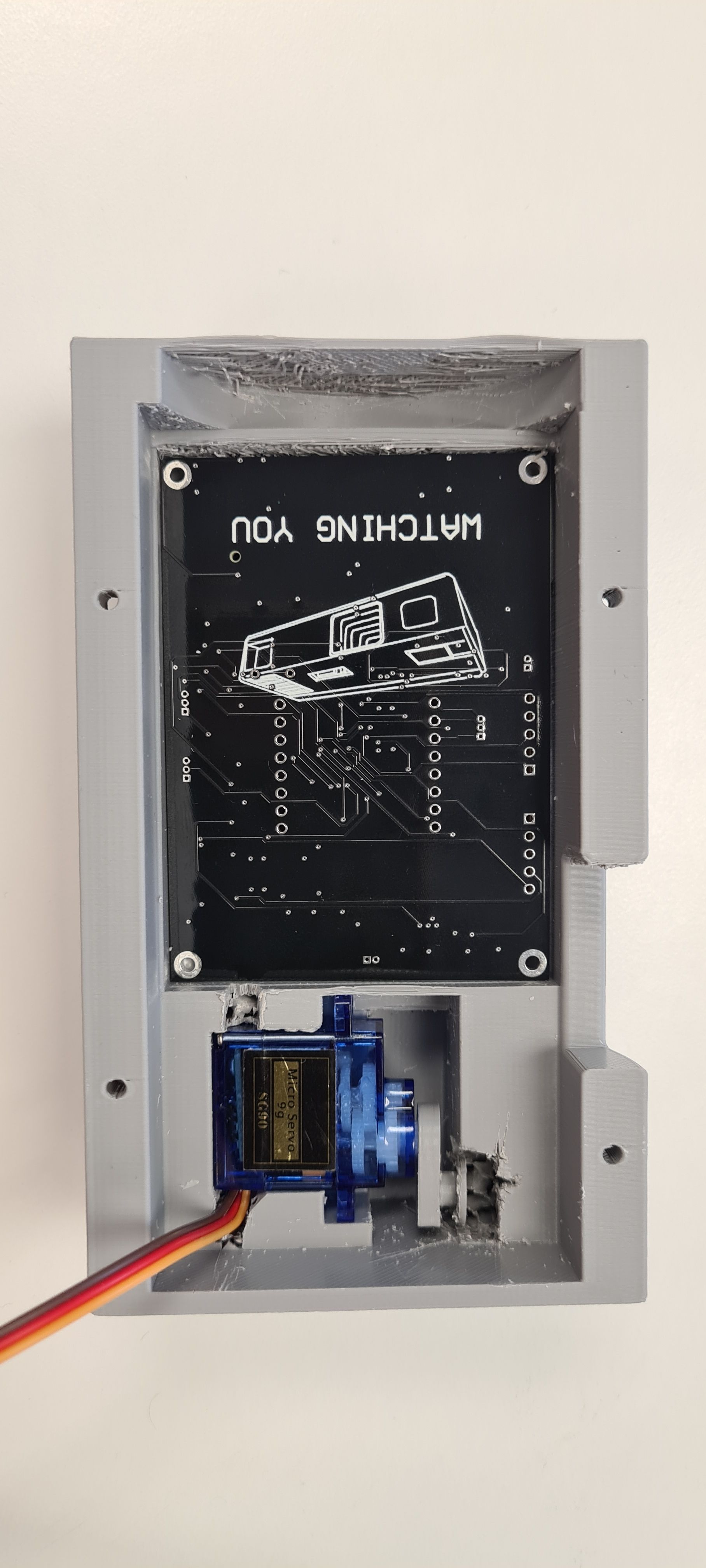
For implementing, we decided on using an SG-90 servo for both the trigger and film advance, simply modding the latter to turn it into a geared down DC motor. To sense the current, we just needed a nice little bit of first-year opamp analysis to calculate a circuit to measure current.
After all, if it didn’t work, we always had the next iteration to get it right. This is what we call foreshadowing.
Mechanical
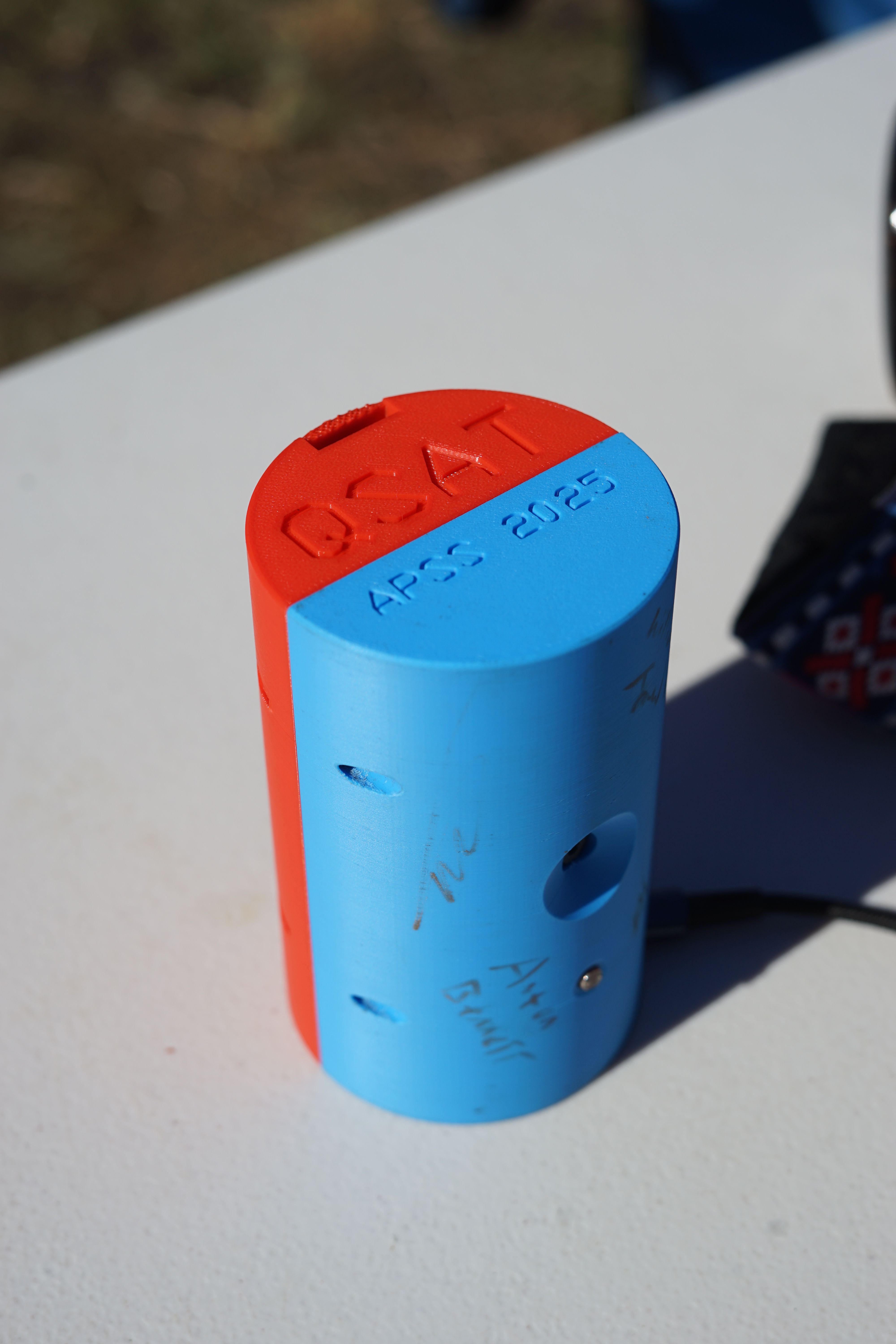
Constraints: The payload must fit within the I class rocket. The airspace that can house the payload has a maximum height of 125 mm and a maximum width/diameter of 74 mm. This airspace must also have room to hold the parachute when it’s not being deployed. The payload must also eject out from the rocket freely after reaching apogee. The payload must also be able to open and close, so we can access the electronics inside. Relative to the total space available, the film camera was massive, at 114.512 mm x 55 mm x 26.1 mm.
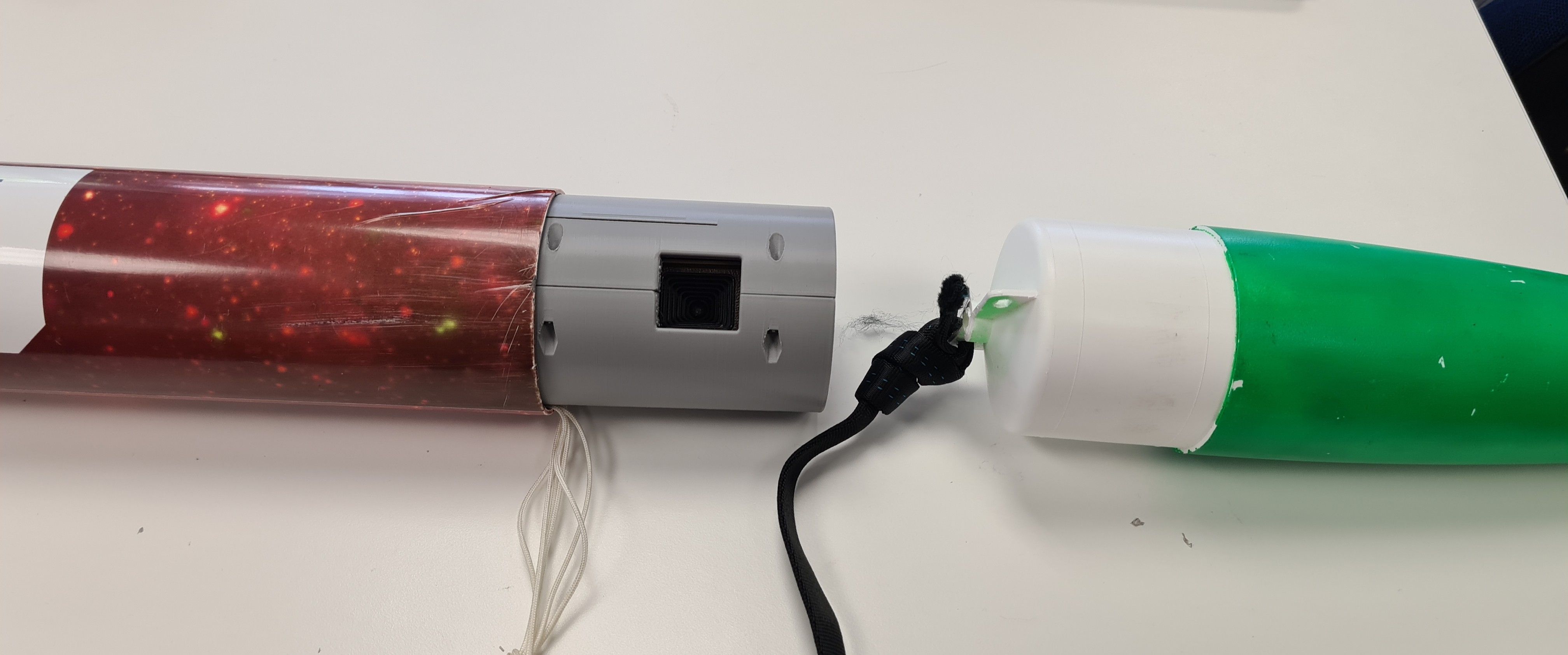
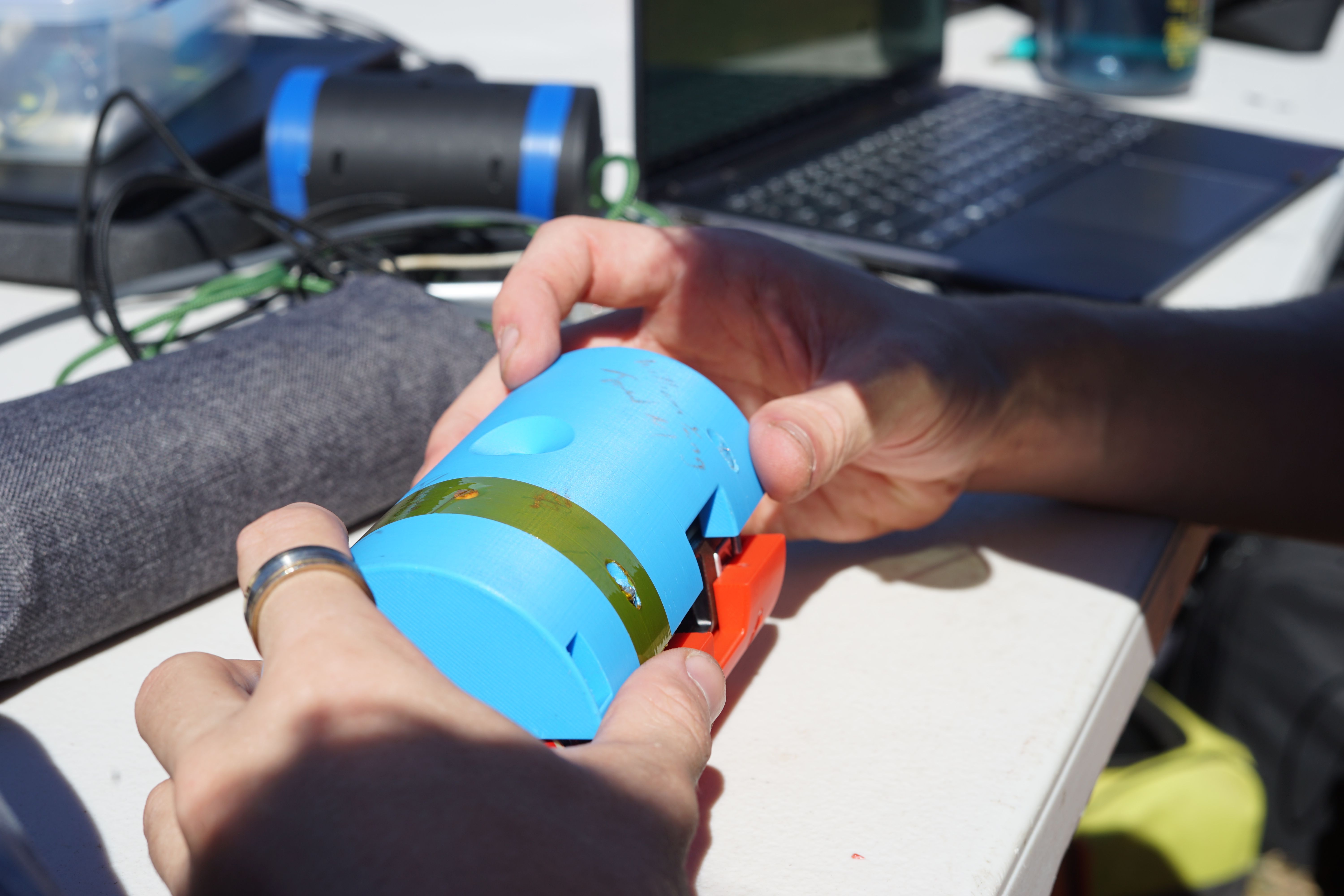
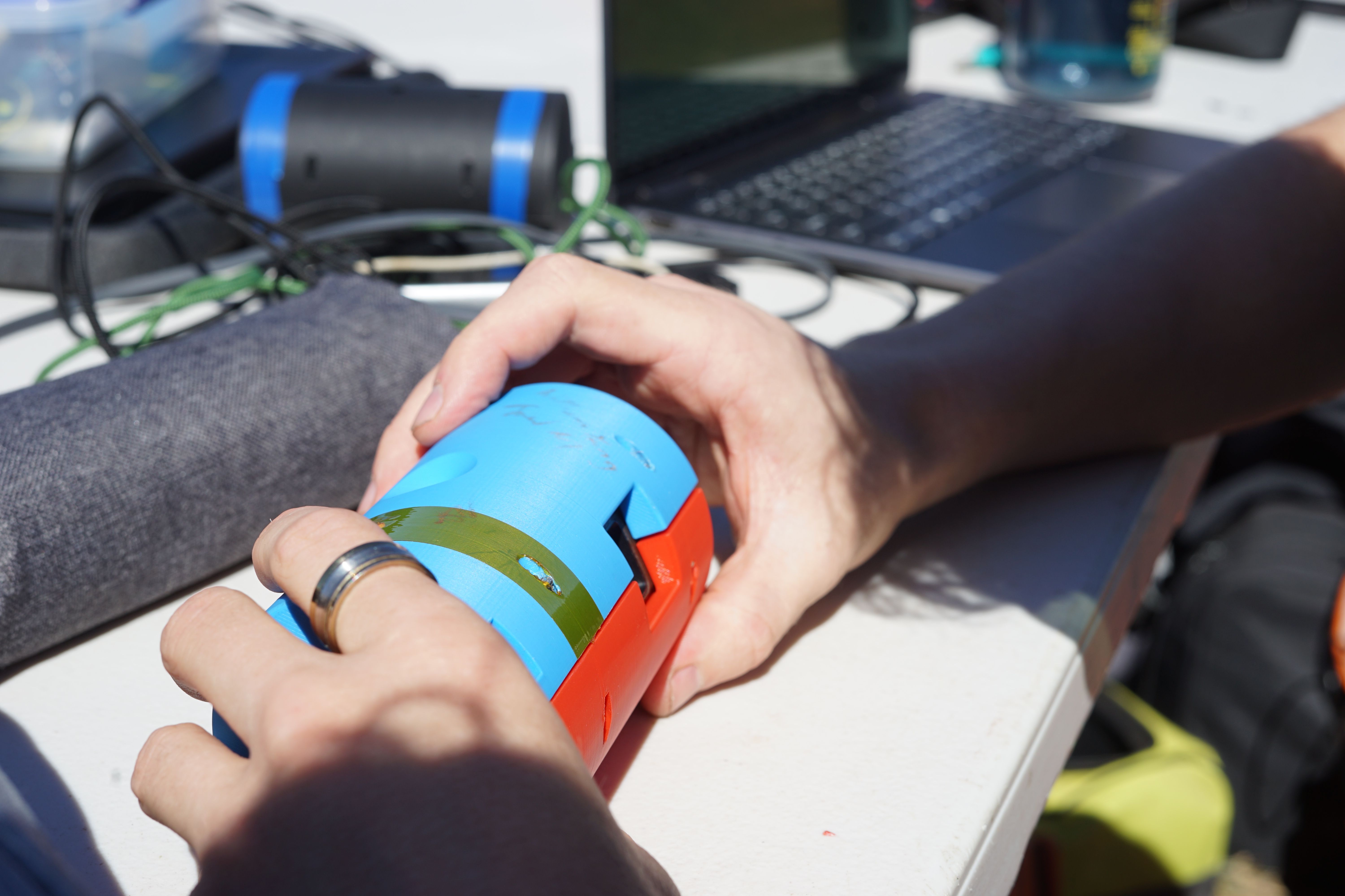
We used the camera as the core of our payload, and designed around it in the remaining space. Two 3D printed shells would bolt on either side of the camera, each holding their respective half of the components. On one side of the camera, we placed the battery with the film advance servo, and the other housed our long custom PCB with the trigger pushing servo.
As a result of us maximising the rocket tube’s airspace, we had to come up with an idea on how we could attach the parachute to our payload. Since we weren’t able to attach a mount on the top or bottom end of our payload, we decided to mount our parachute on the side of the payload, not through an external mount. We had enough space inside the payload that we could make a small channel that allowed us to feed the parachute strap through.
Version 0
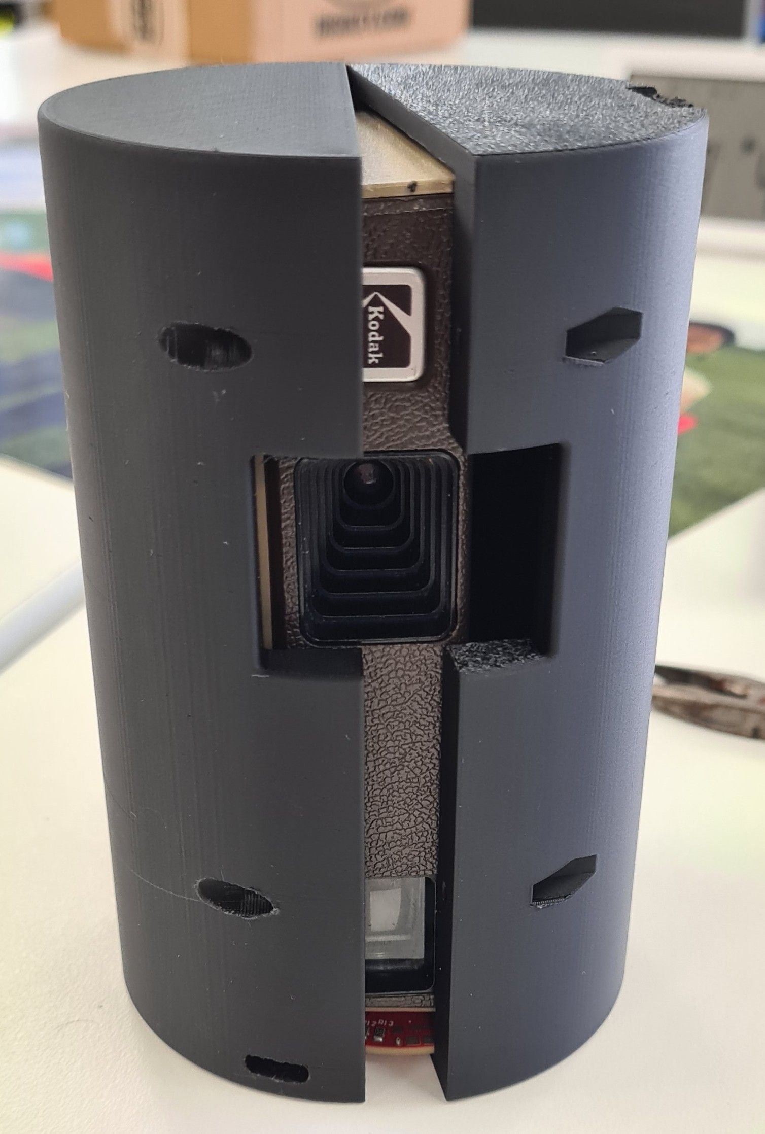
‘Version 0’ was our initial proof-of-concept to make sure our film camera could fit inside our allocated payload size. We 3D printed a cylinder with the area for the camera cut out of the inside. The benefits of doing this allowed the whole team to get an idea of area around the camera we have to work with, and with the CAD model we could start allocating space for different elements.
Version 1
With version 1 we began exploring size and placement of elements. We knew roughly what elements were going into the payload, so we were able to cut out the space for them. This allowed us to explore whether the internal structure would hold with so much material cut out. This included performing drop tests and general structural tests. Another element that was explored was how we can open & close the payload. This problem is nontrivial as the payload must retain its outer cylindrical form, and a top cap could not be used as the internal structure of the payload could not all be accessed. So the idea for a clamshell mechanism was tested. The payload shell was split vertically, with holes to allow 4 bolts to hold the shell together. Another benefit of this design was, with the camera removed, all internal electronics were easily accessible to run wires.
Version 2
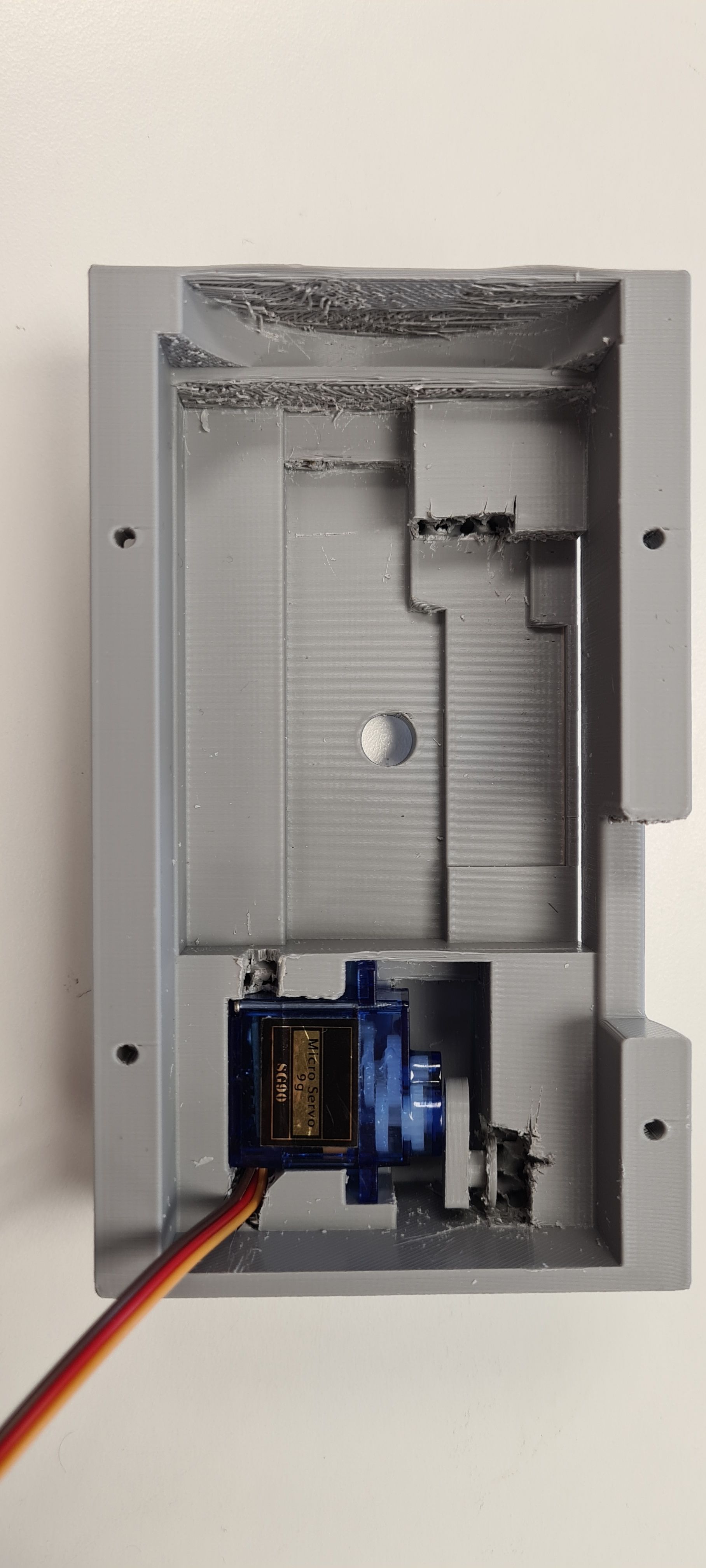
Airspace surrounding the space where the servos would go were expanded for allowing a better fit of the the servos. Airspace created at the base of the interior of the shell to allow for placement of the PSU board. Cutouts were made in front of the location where the film camera lens were going to look out from. Cutout also made for the ESP-32 Cam lens to look out through.
After attempting to place the servos into their dedicated spot, the airspaces were found to still be too tight. Modifications were temporarily made by removing some of the supporting walls inside using a scalpel.
Version 3
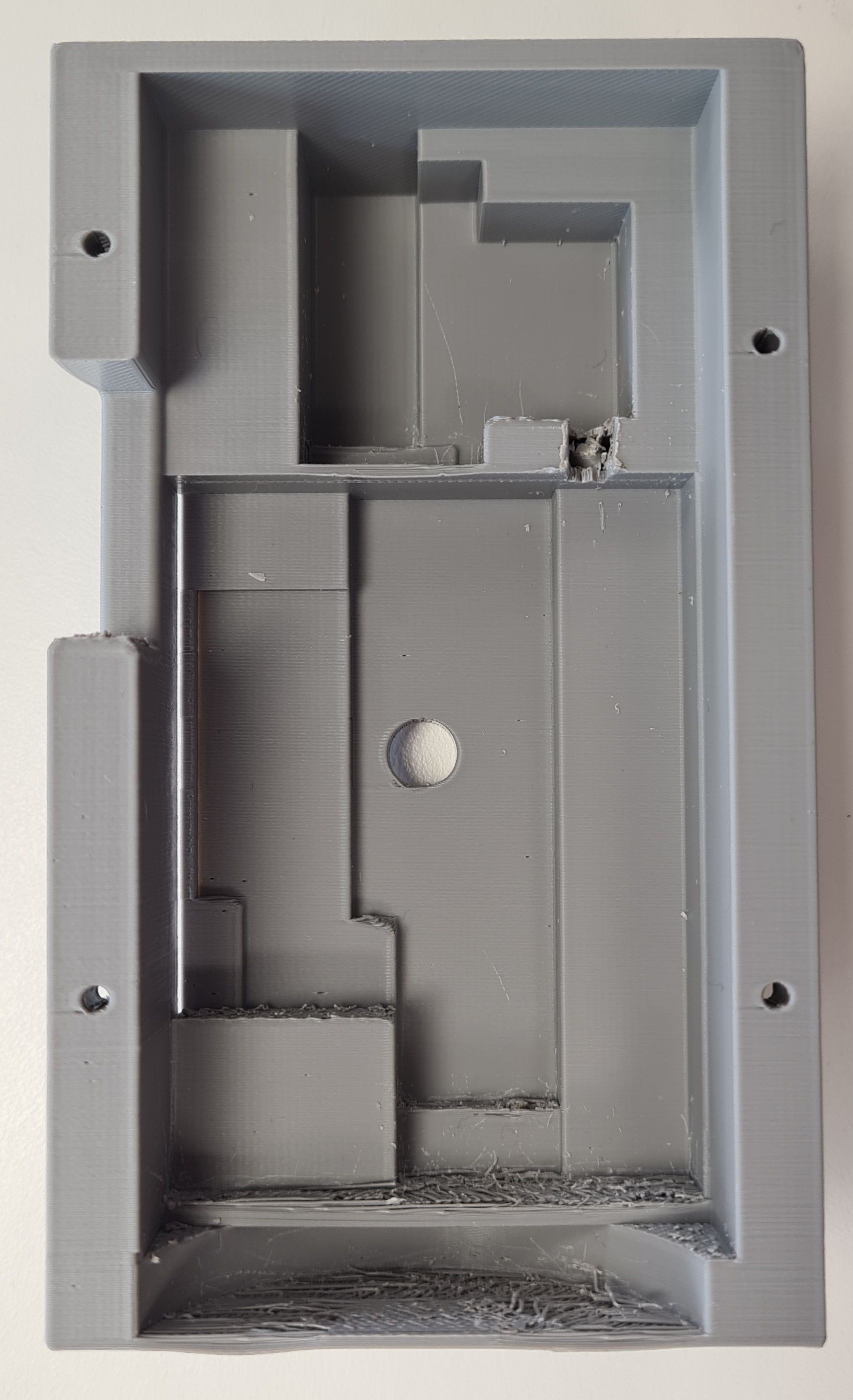
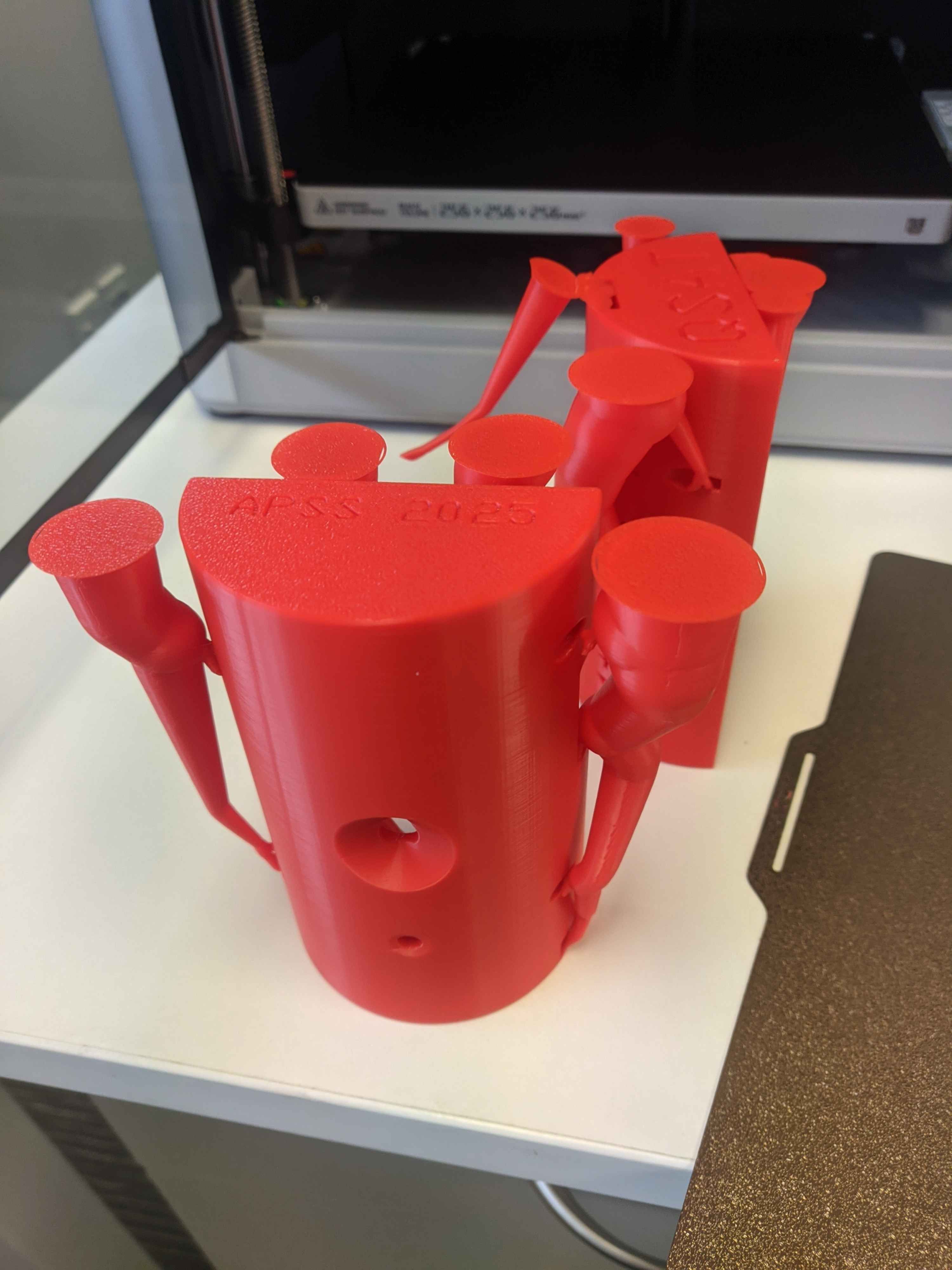
Version 3 was 3D printed with larger airspaces for the servos.
Version 4
Version 4 was 3D printed with larger airspaces for the servos.
Version 4.5
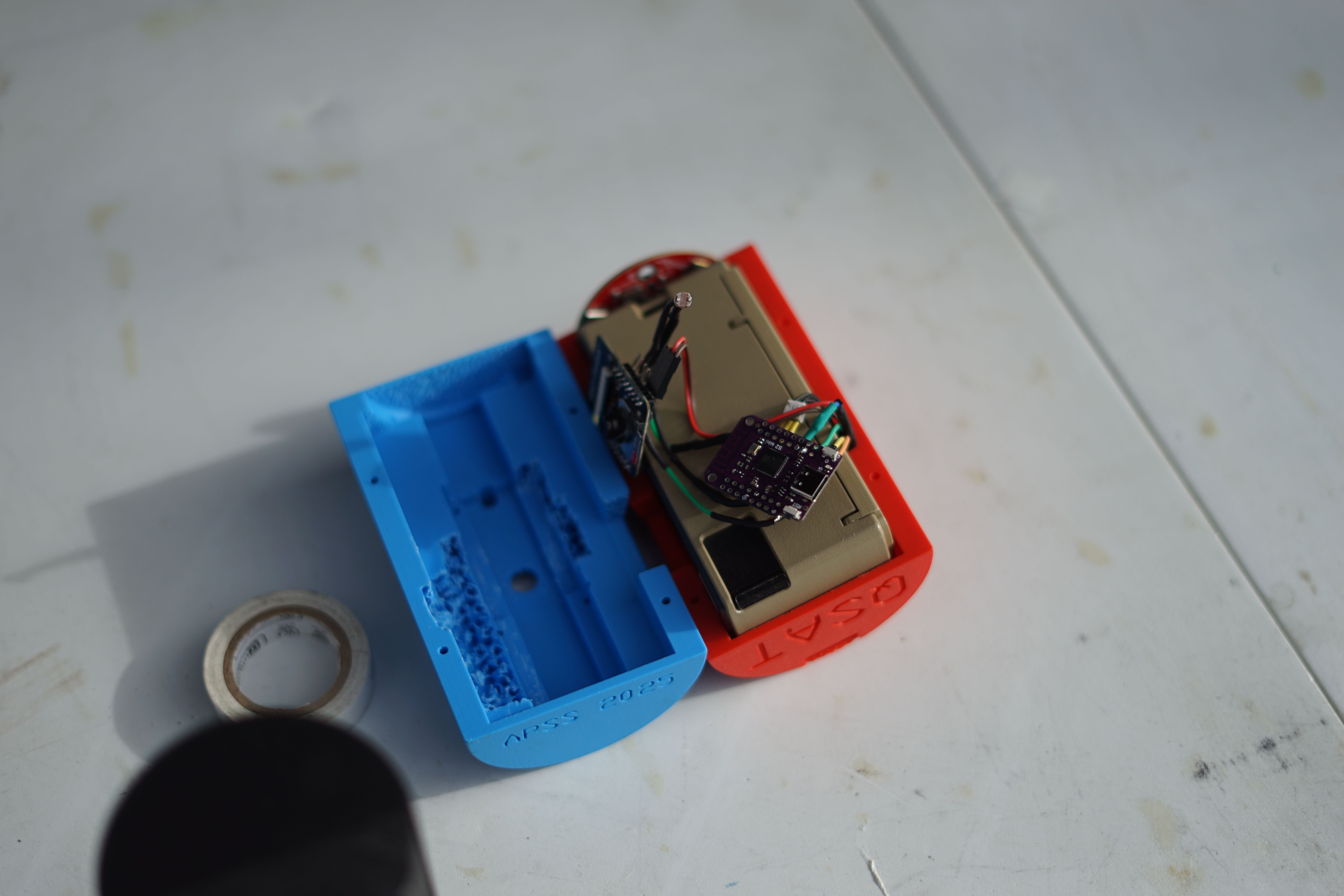
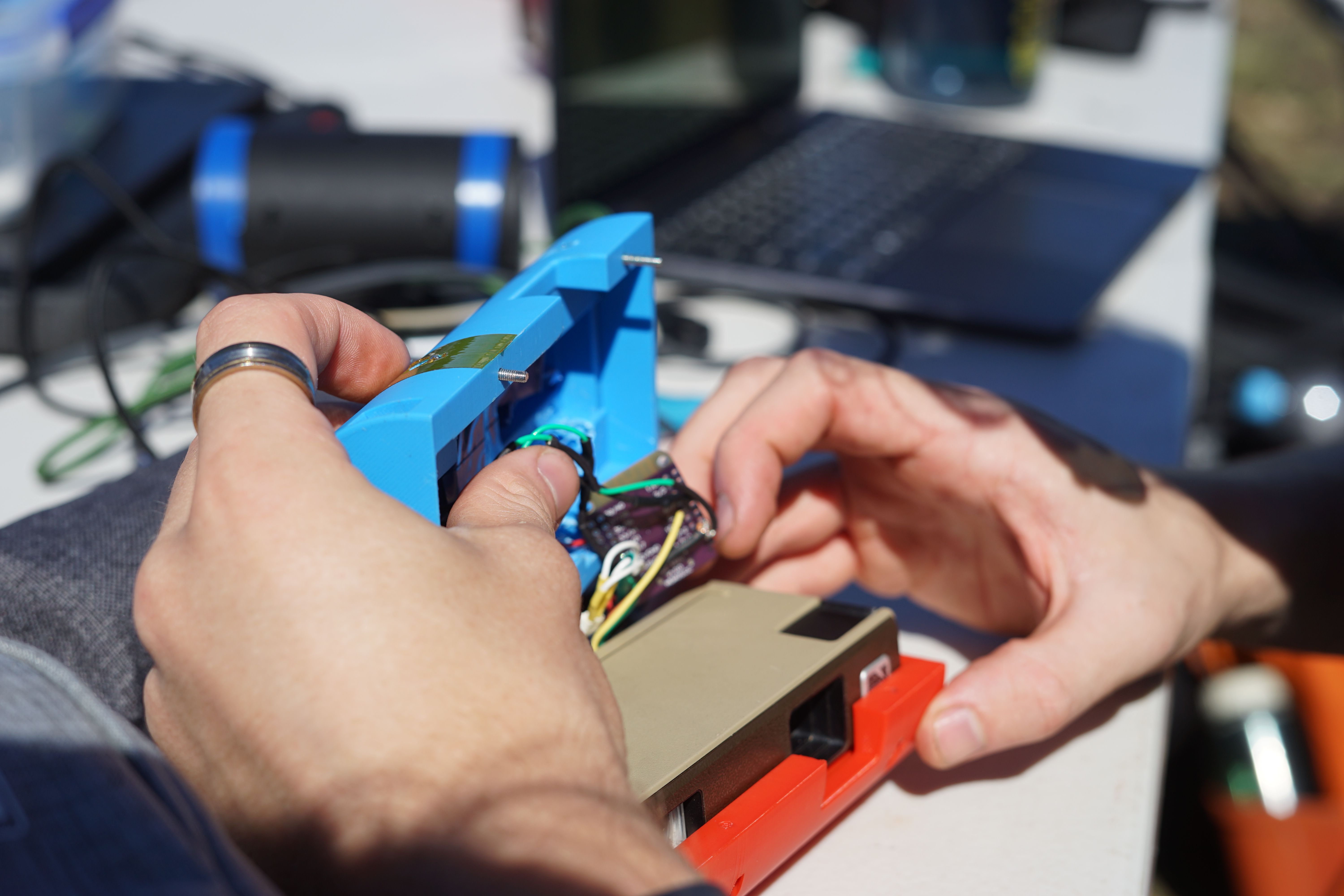
Due to the sudden demise of our custom PCB one week before launch day, we had to scope-down our setup to use a single ESP32 S2 as the core. This meant we had to change interiors of the shell that was designed to house the custom PCB, to now house a series of individual modules jankily wired together.
Preliminary Design Review
The first design review was held on the 1st of December 2024. We presented our concept to the APSS team and received valuable feedback.
Second Iteration
Critical Design Review
Electrical fail
Third Iteration
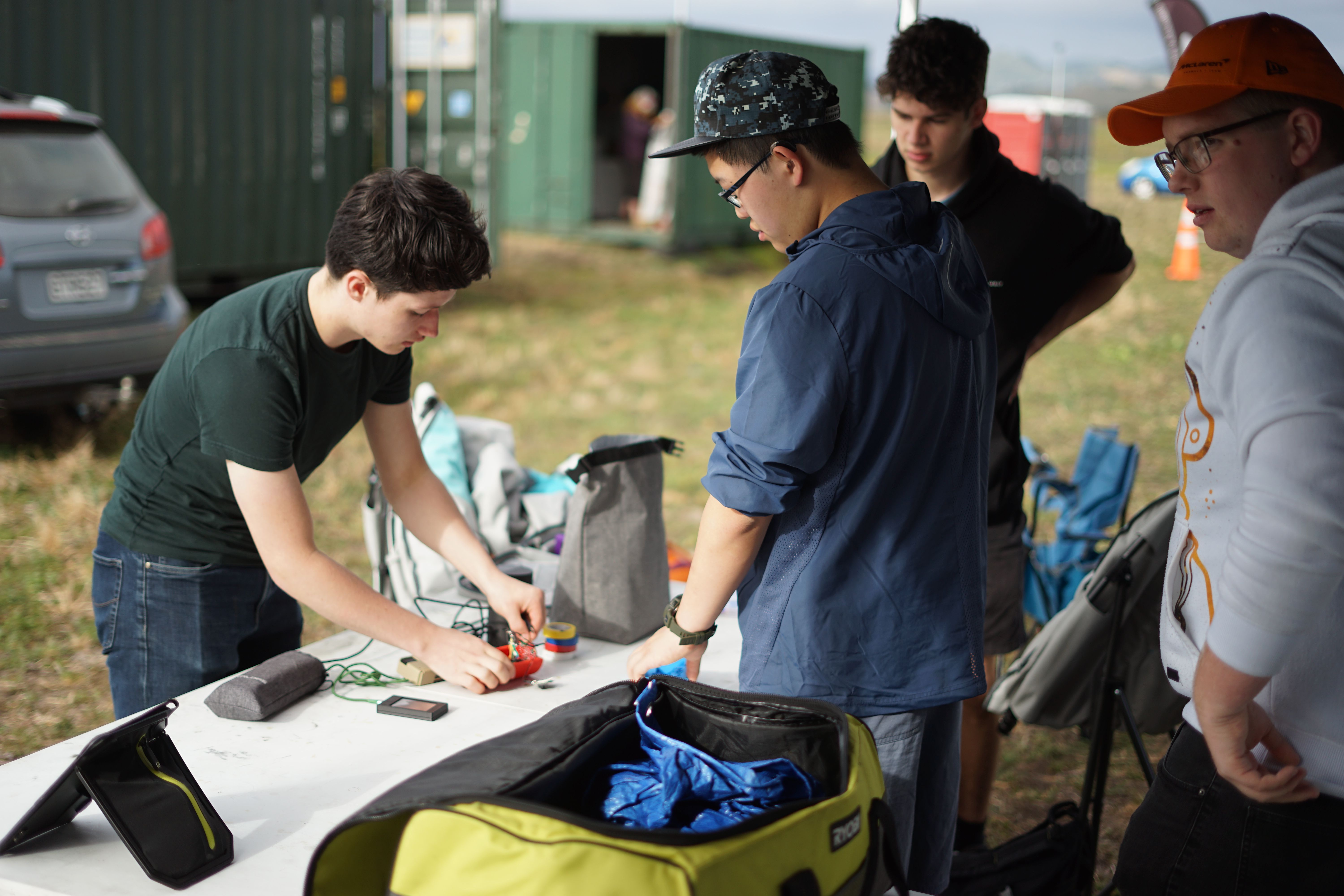
The rebuild
So … we don’t have a controller. We’re supposed to launch in four days. This is where our Hackathon experience came in handy.
We split our goals into three sequential scopes:

Priority one was simple. It would simply wait until the payload was ejected into the bright sunlight, then push down the trigger on the film camera. This was the MVP that if functional in time, would make it worth the time to launch the payload.
The next scope, priority two, added a digital camera and power management to the design. Upon ejection from the rocket body, it would enable the 5V rail on the power supply. This would both enable the Servo, and power up the ESP-CAM. The ESP-CAM would take as many photos as possible on boot, and save to the included SD card.
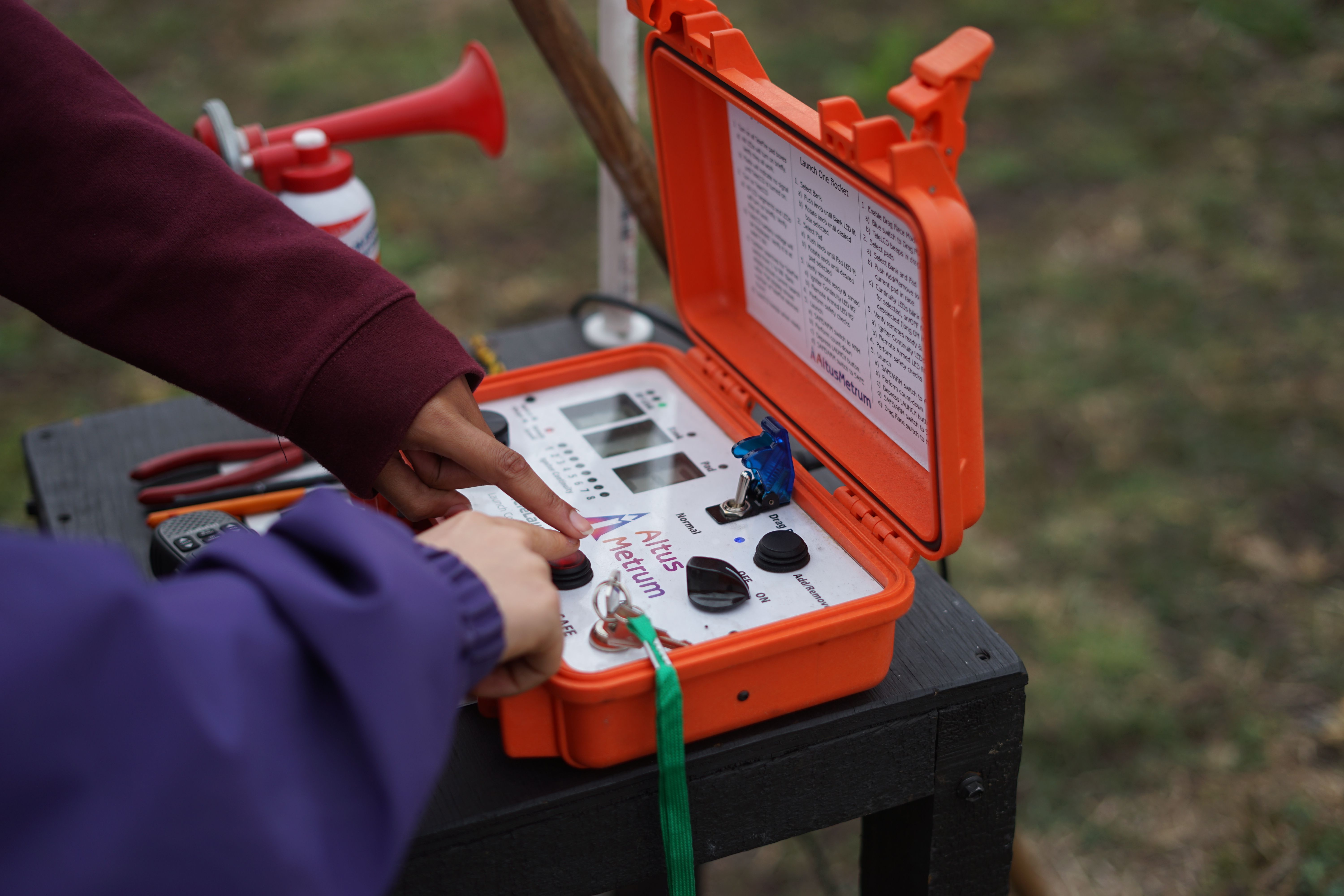
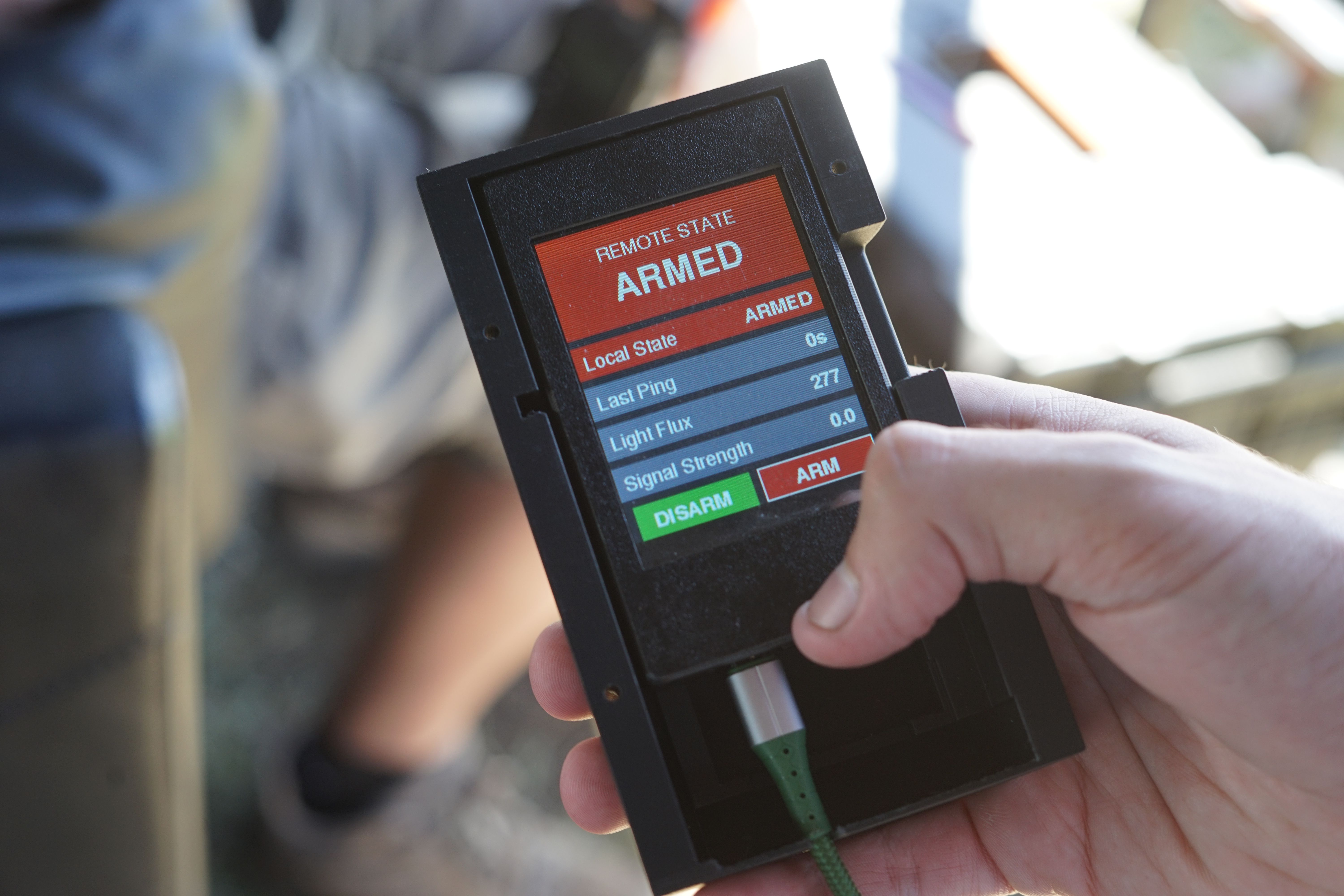
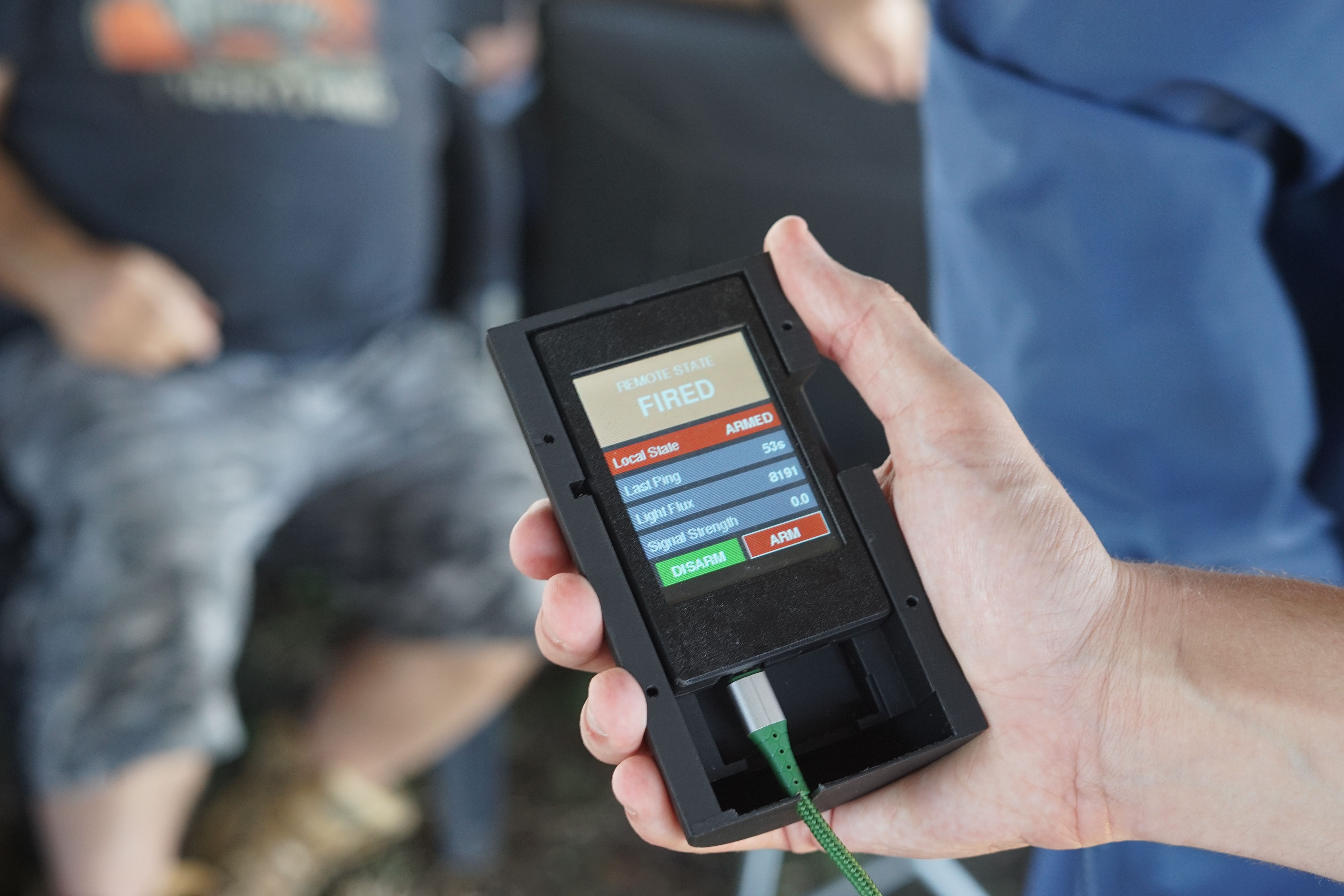
Finally, as our stretch goal in priority three, we wanted remote arming. As we only had a single shot, the worst case scenario was our payload activating prematurely and wasting the film. If we’re constantly looking for light, we would have to arm the payload, and assembly the rocket without any light leaking into the payload.
This is why we choose an ESP32 as the core MCU at the start, as this enabled us to easily communicate over ESP-NOW using the built in antenna. Along with a Cheap-Yellow-Display on hand.
When we say rebuild, we meant it. We went back to basics, getting Priority One underway immediately.
Spoilers: We managed to get all of these working, and the remote looks amazing. Take a look:


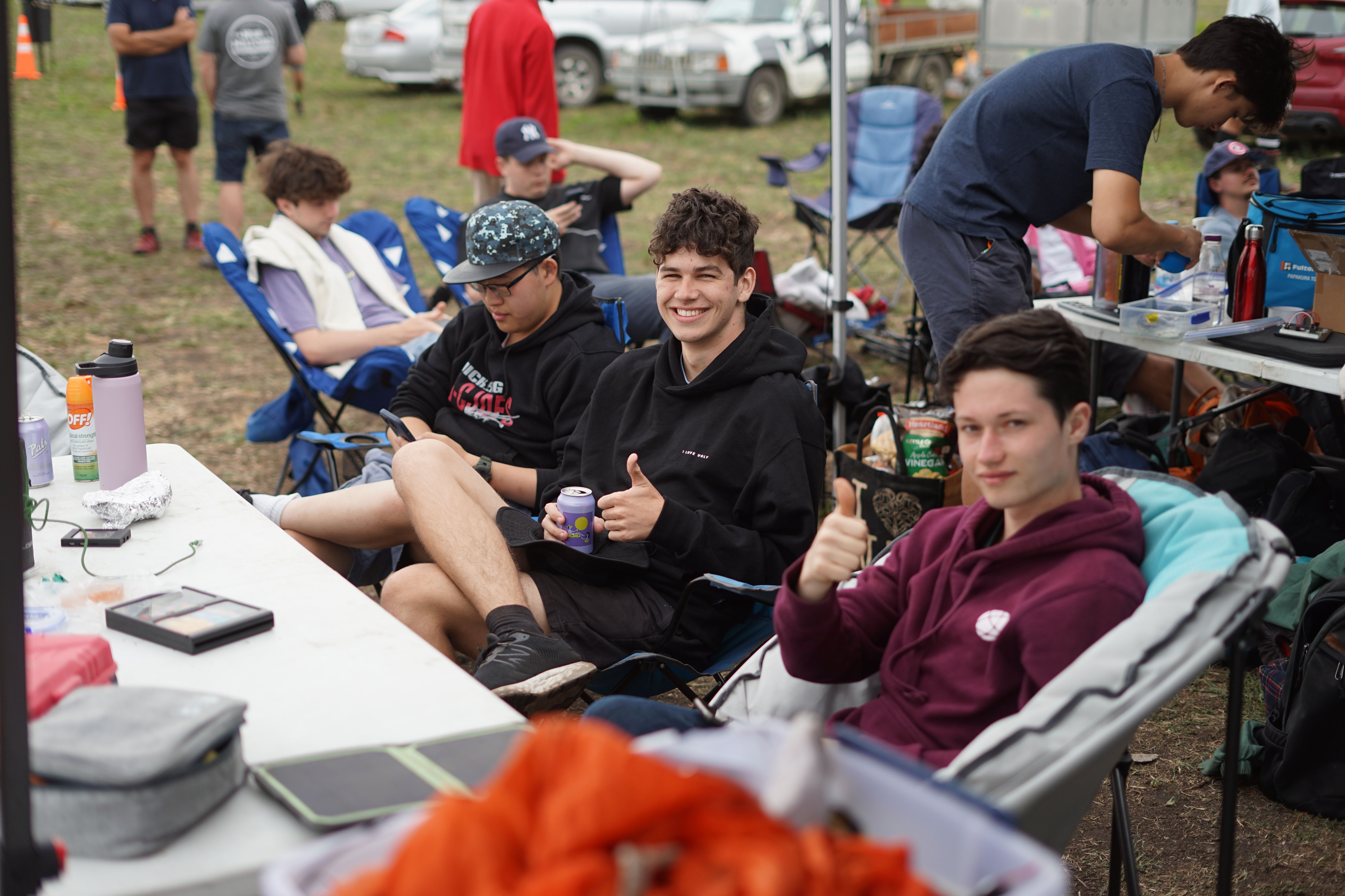
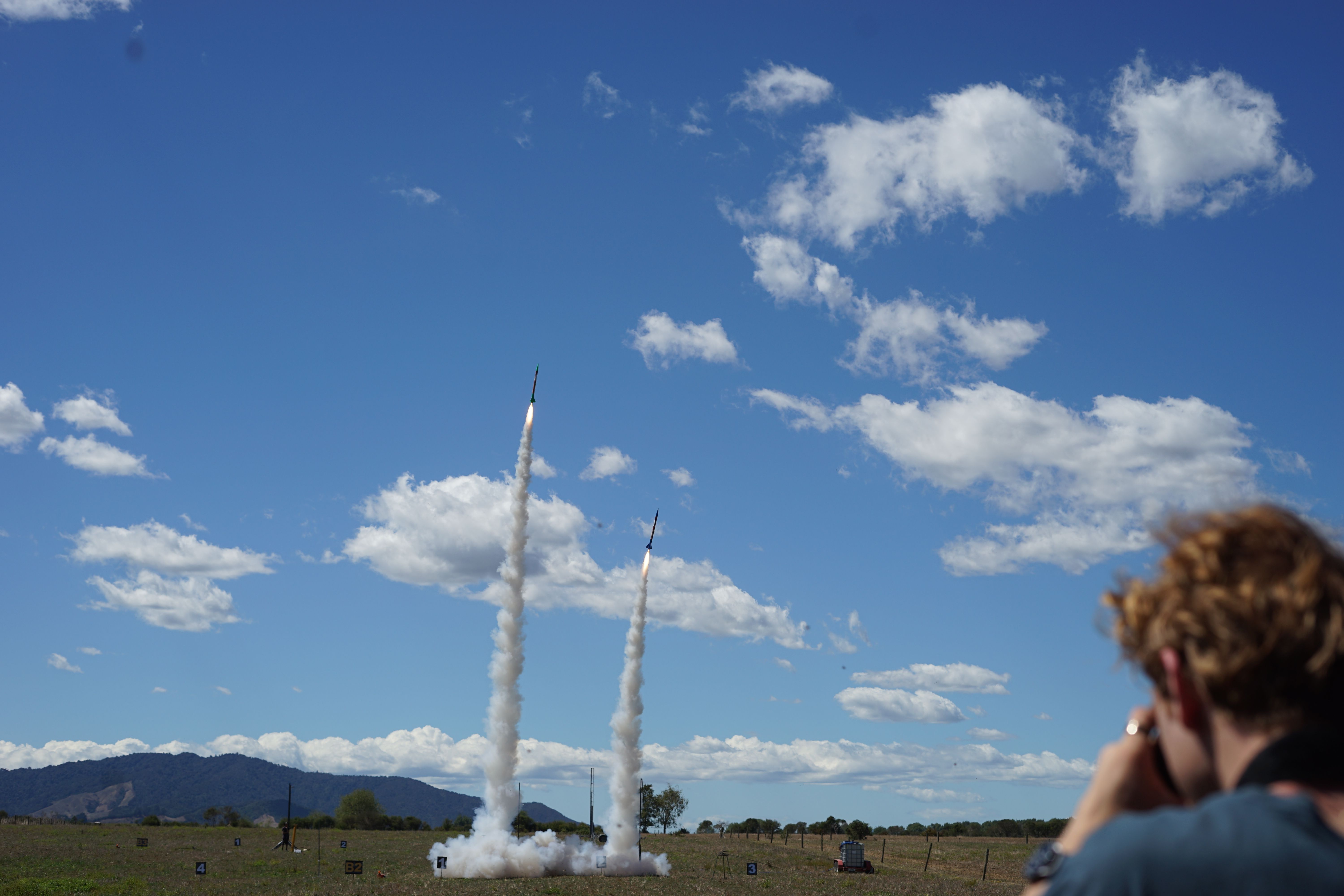
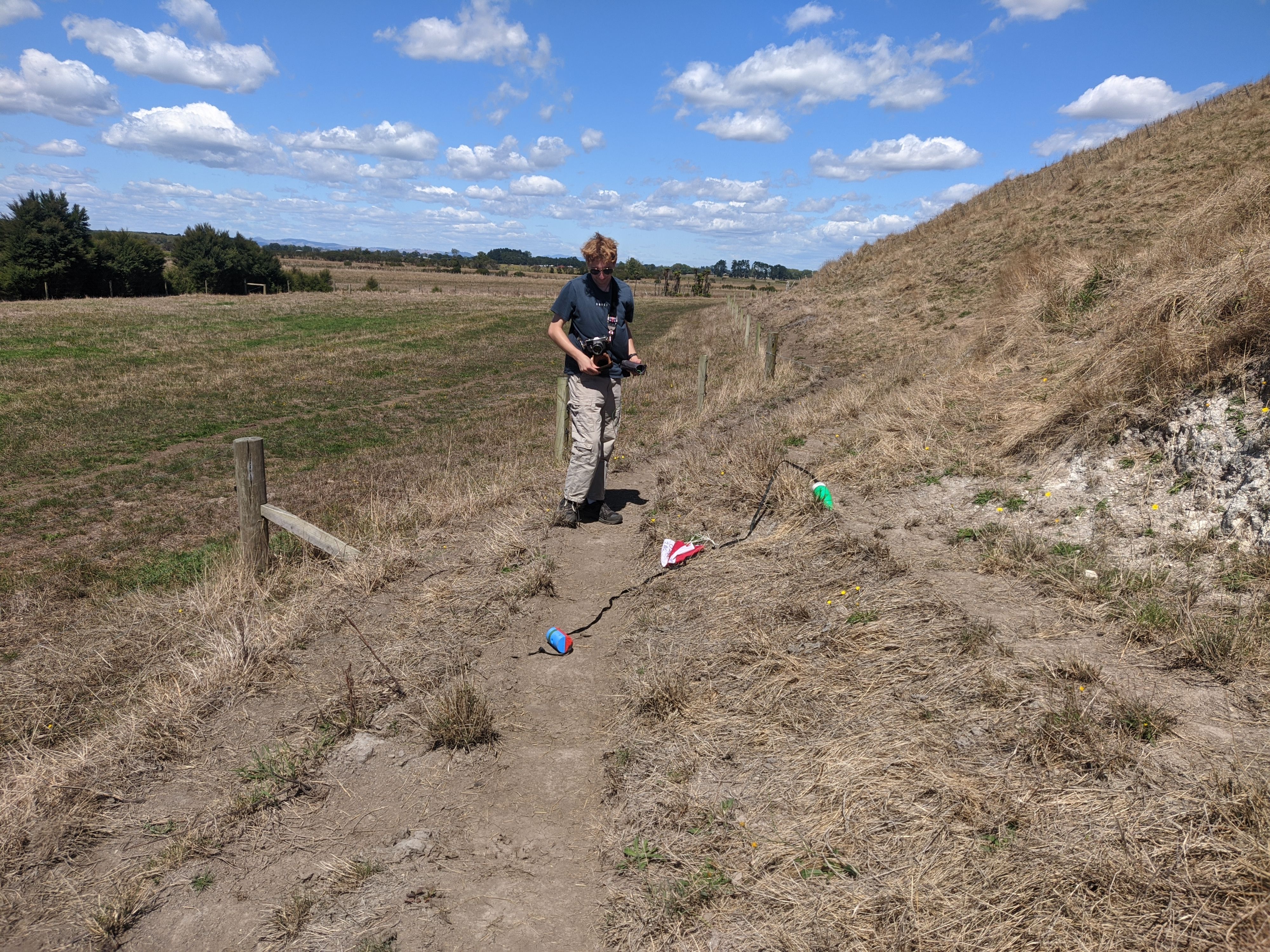
Launch Day
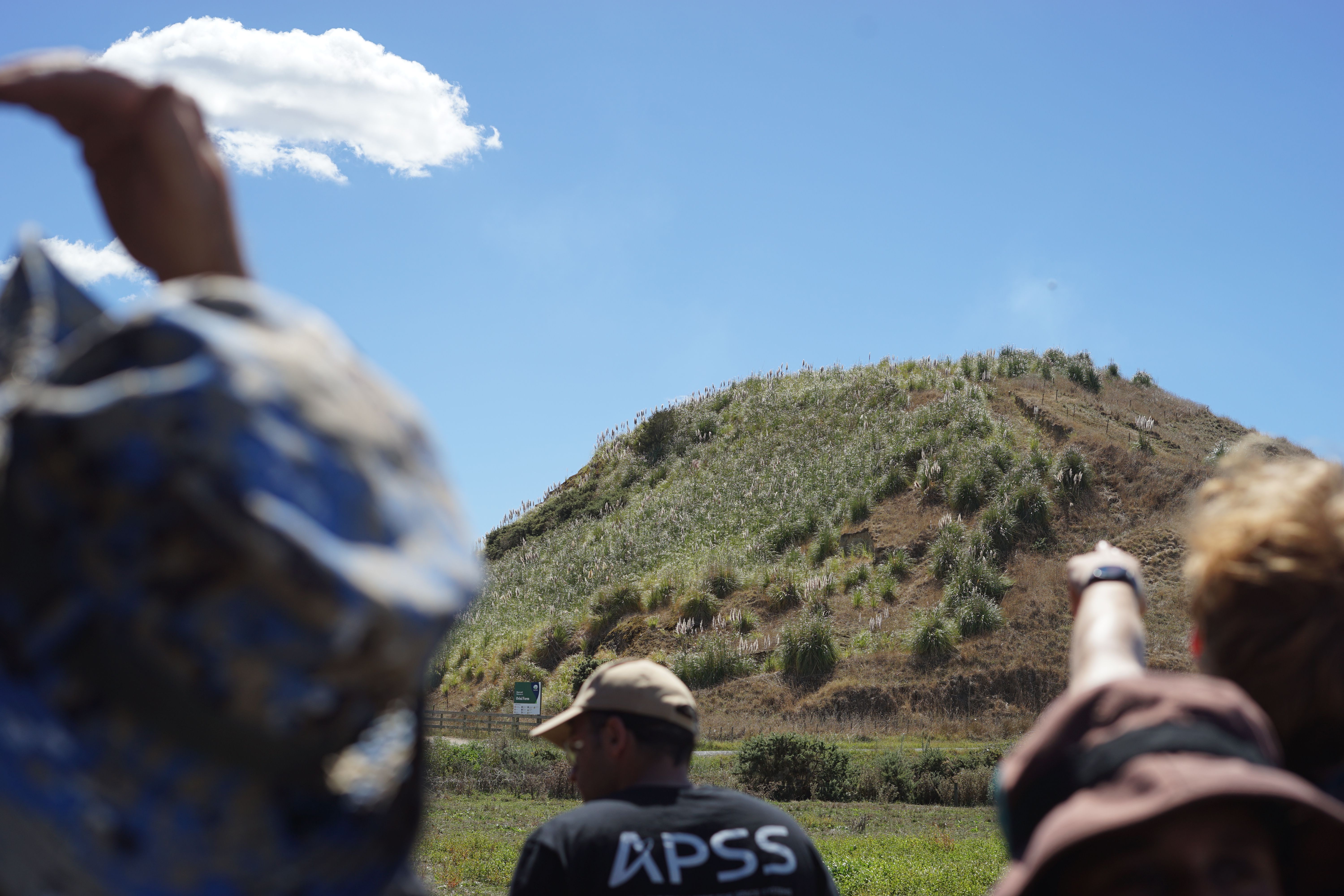
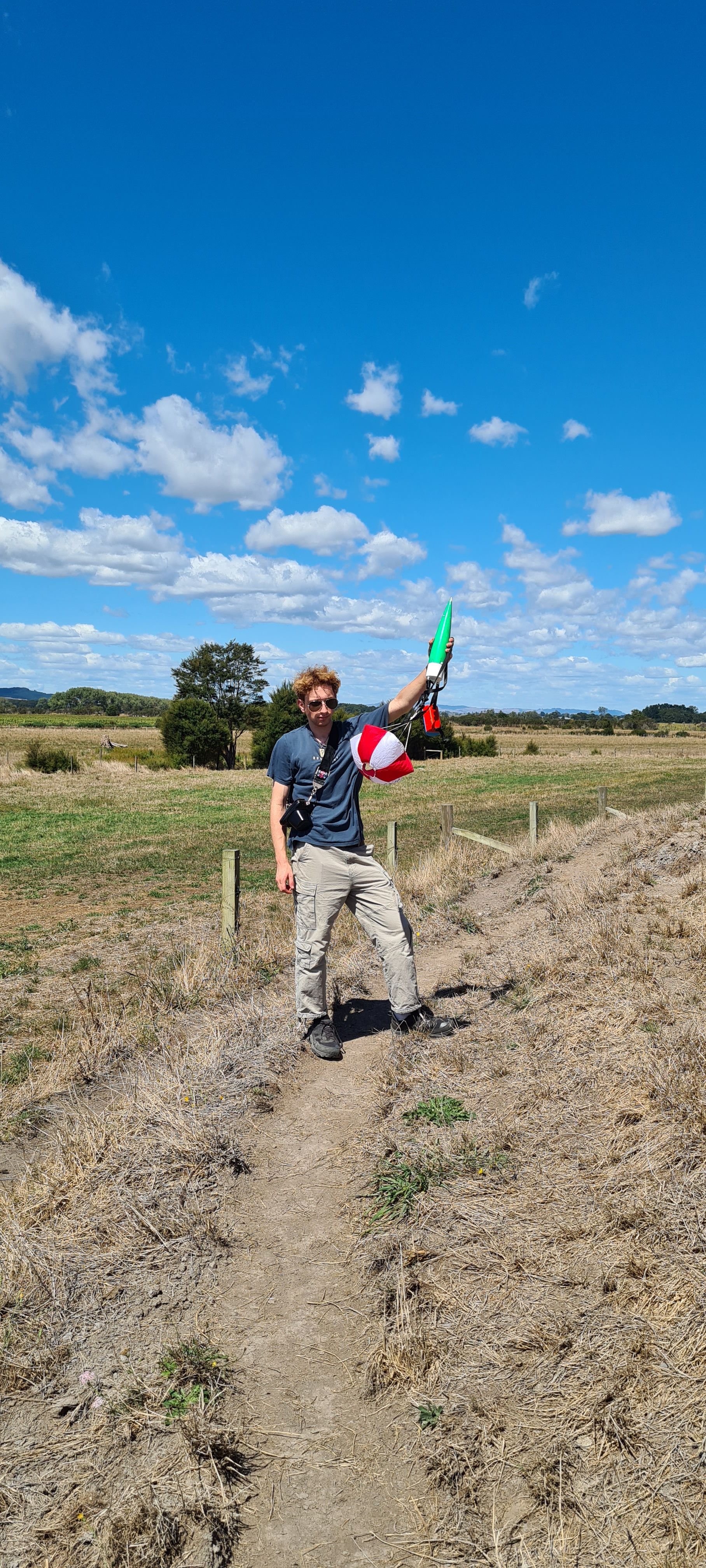
Recovery

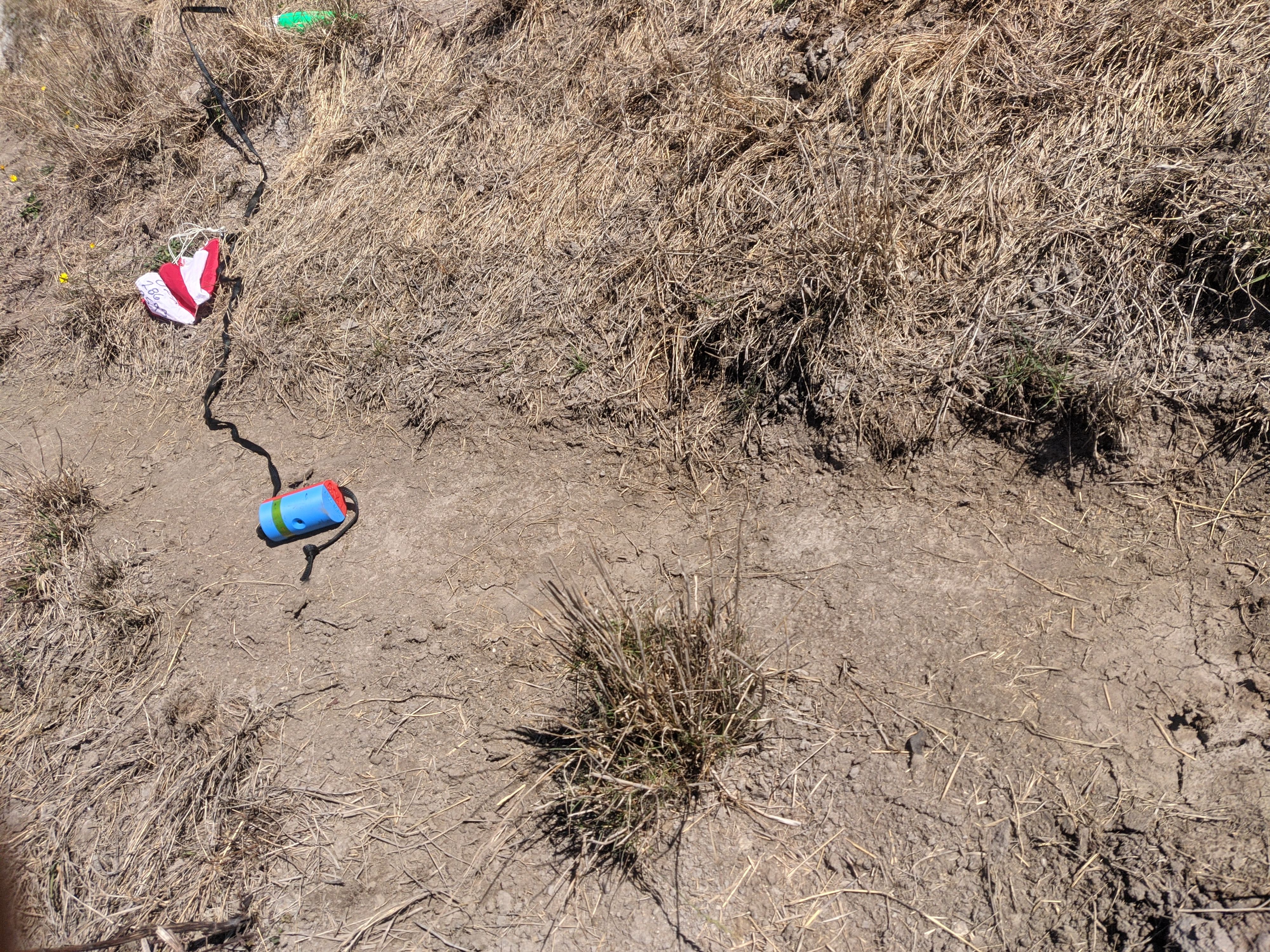
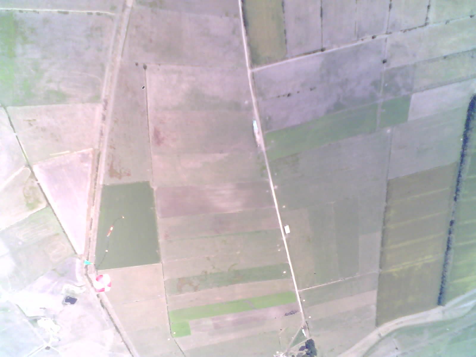
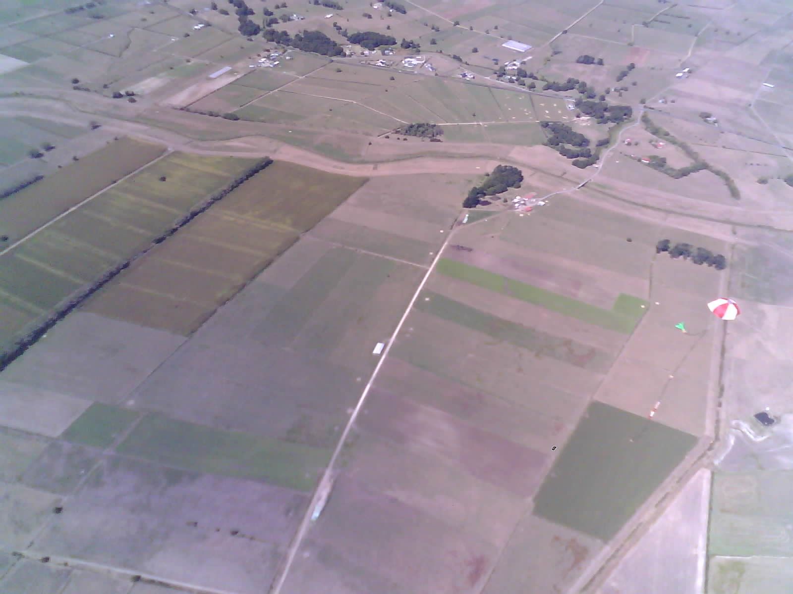
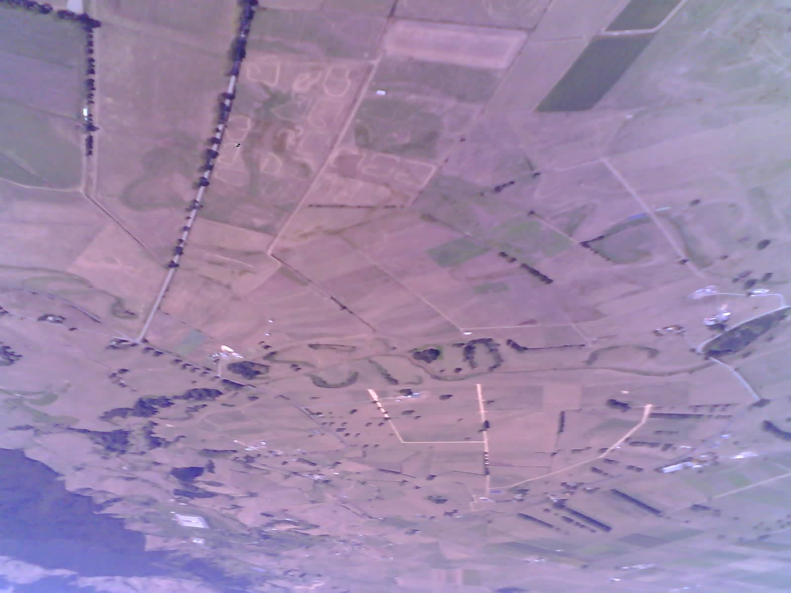
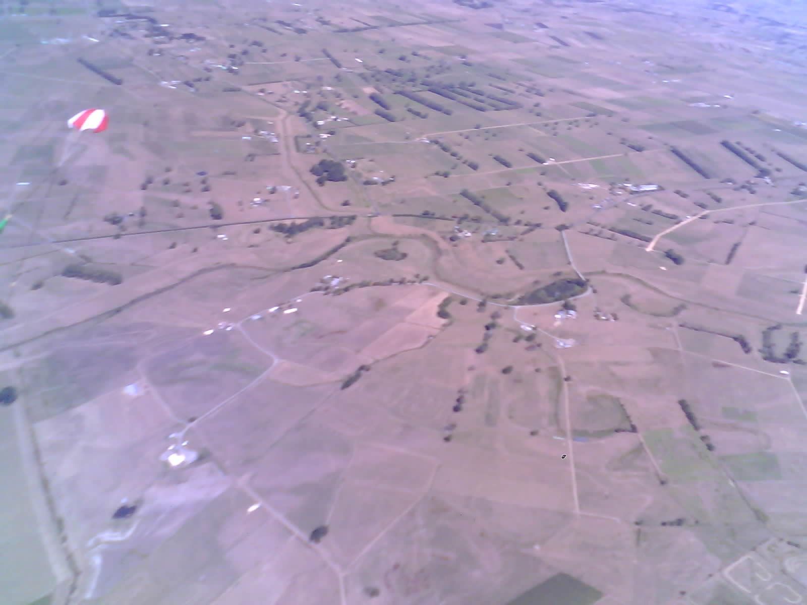
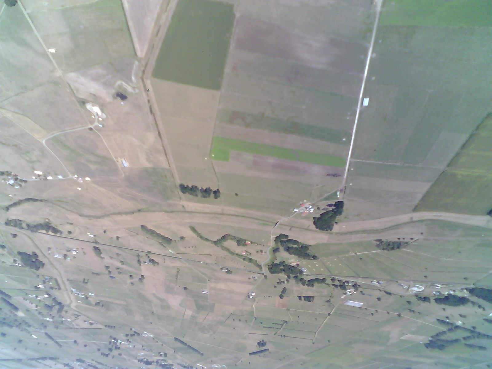
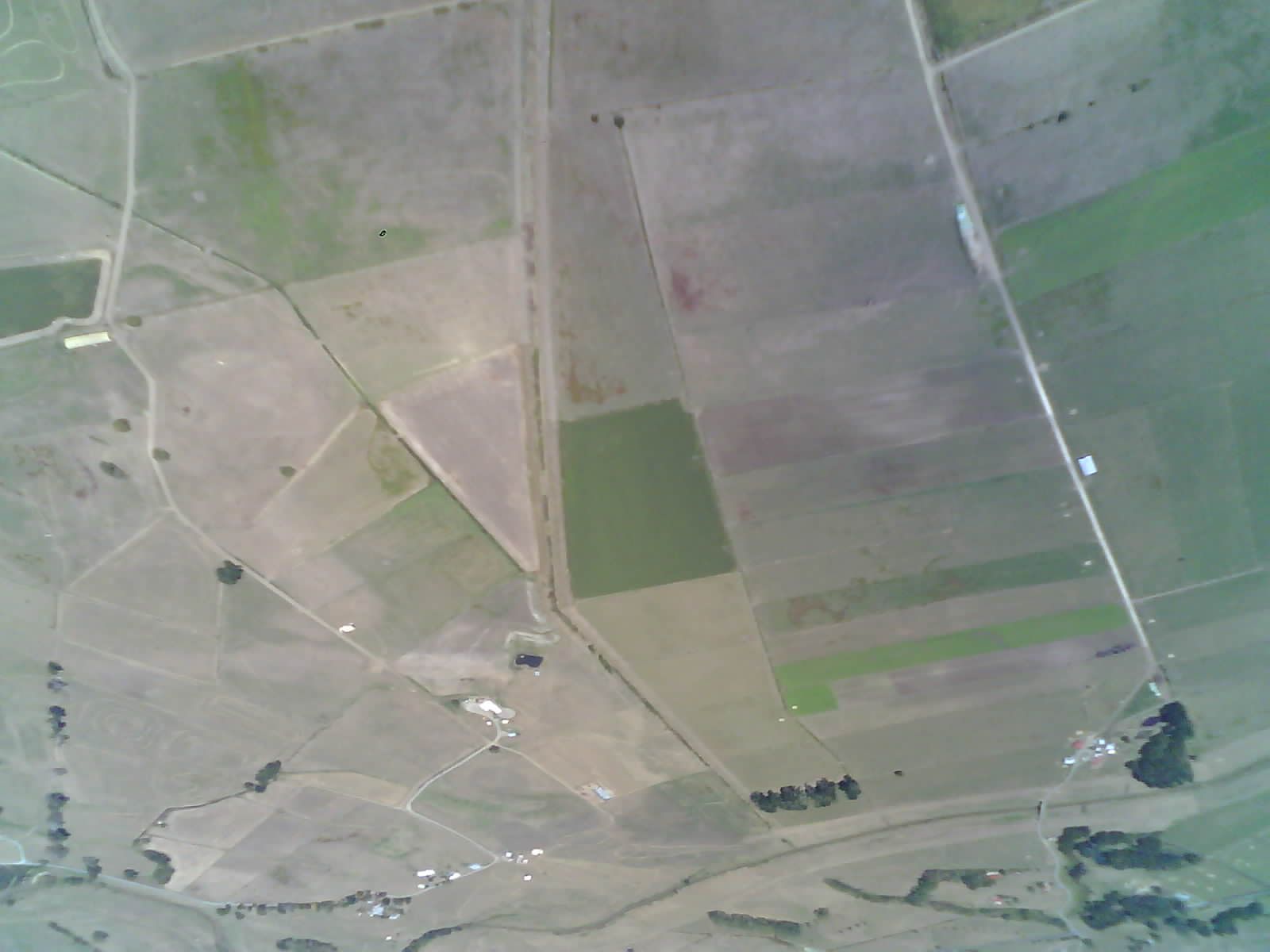
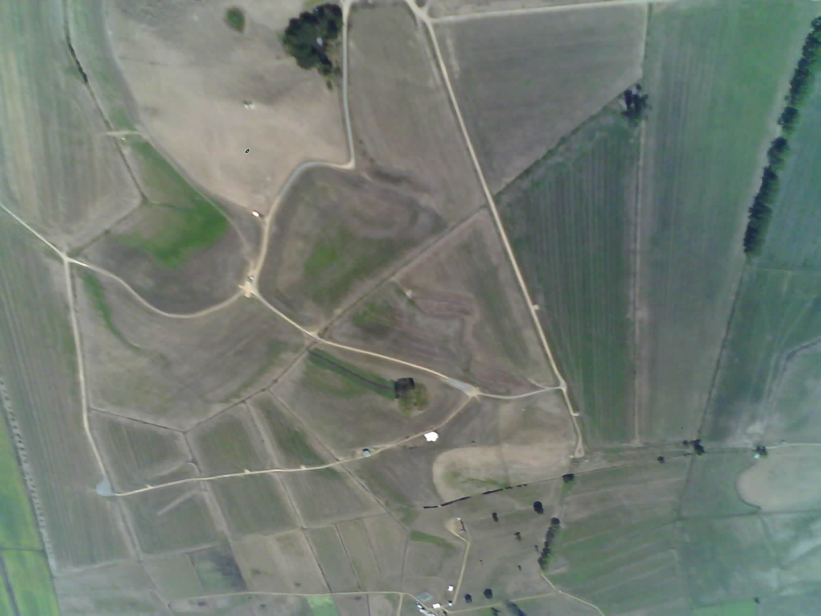
Photos captured
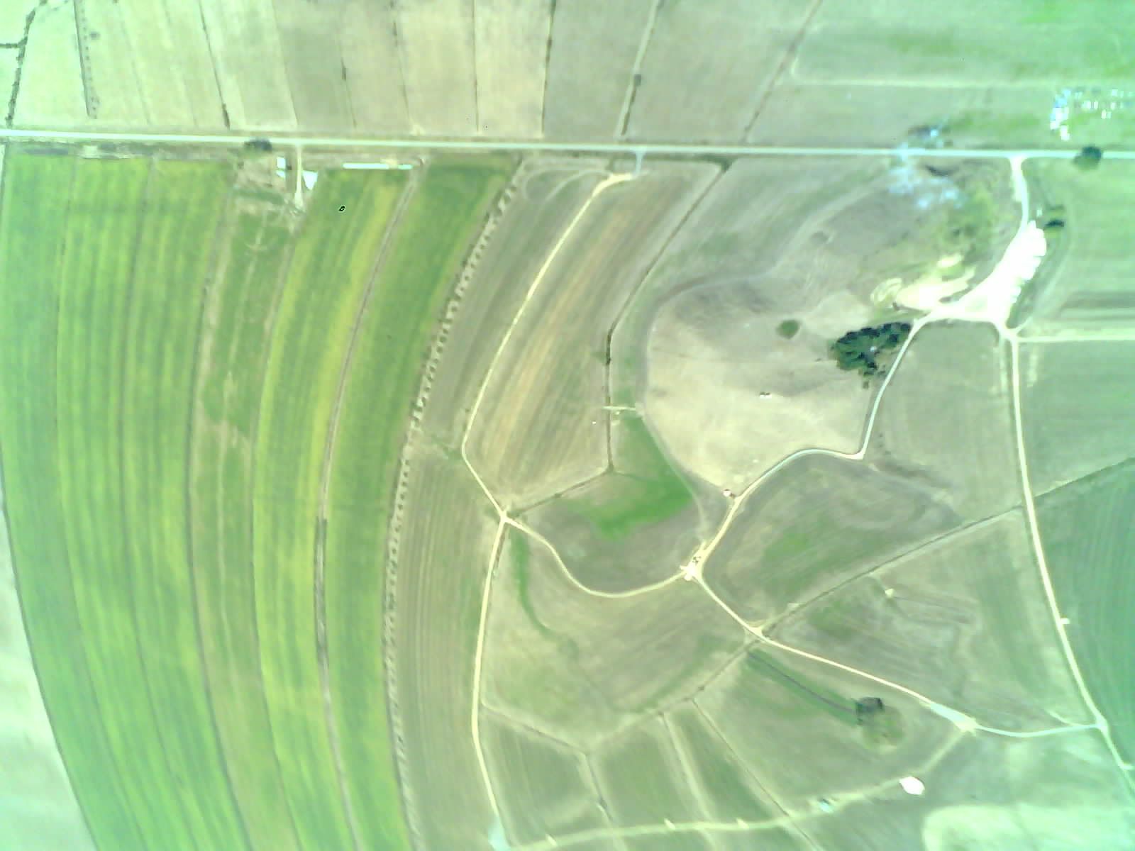
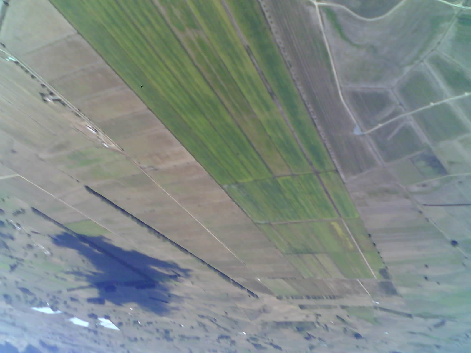
High Speed Footage
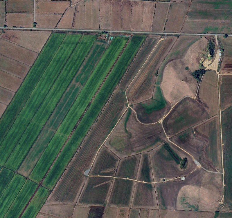
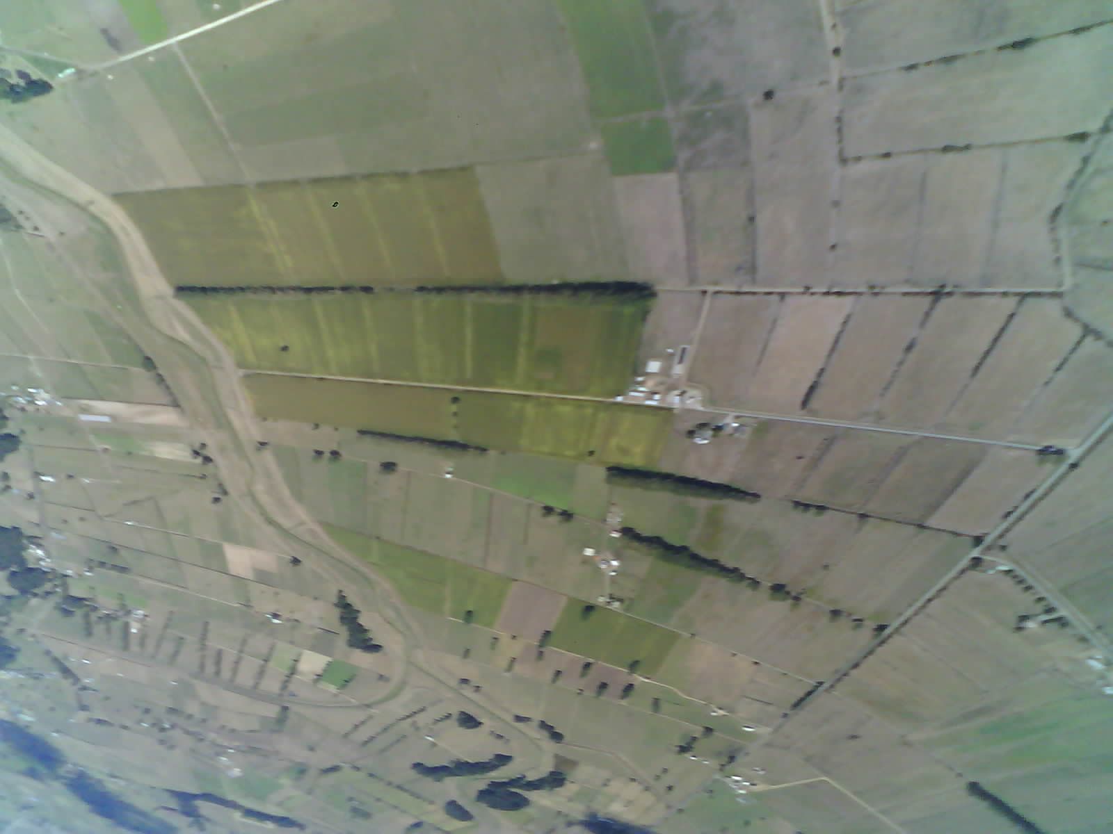
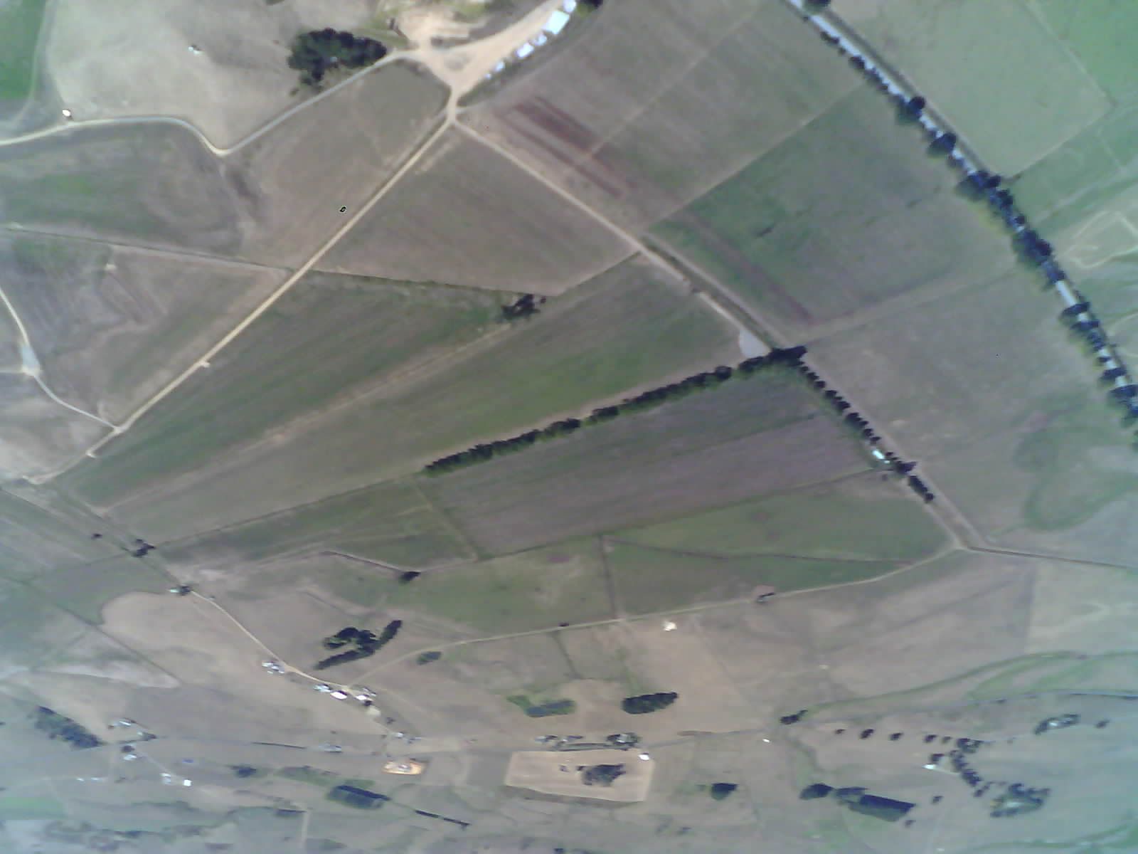
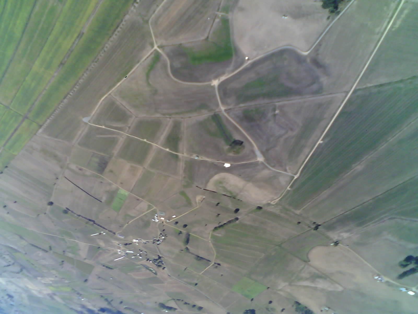
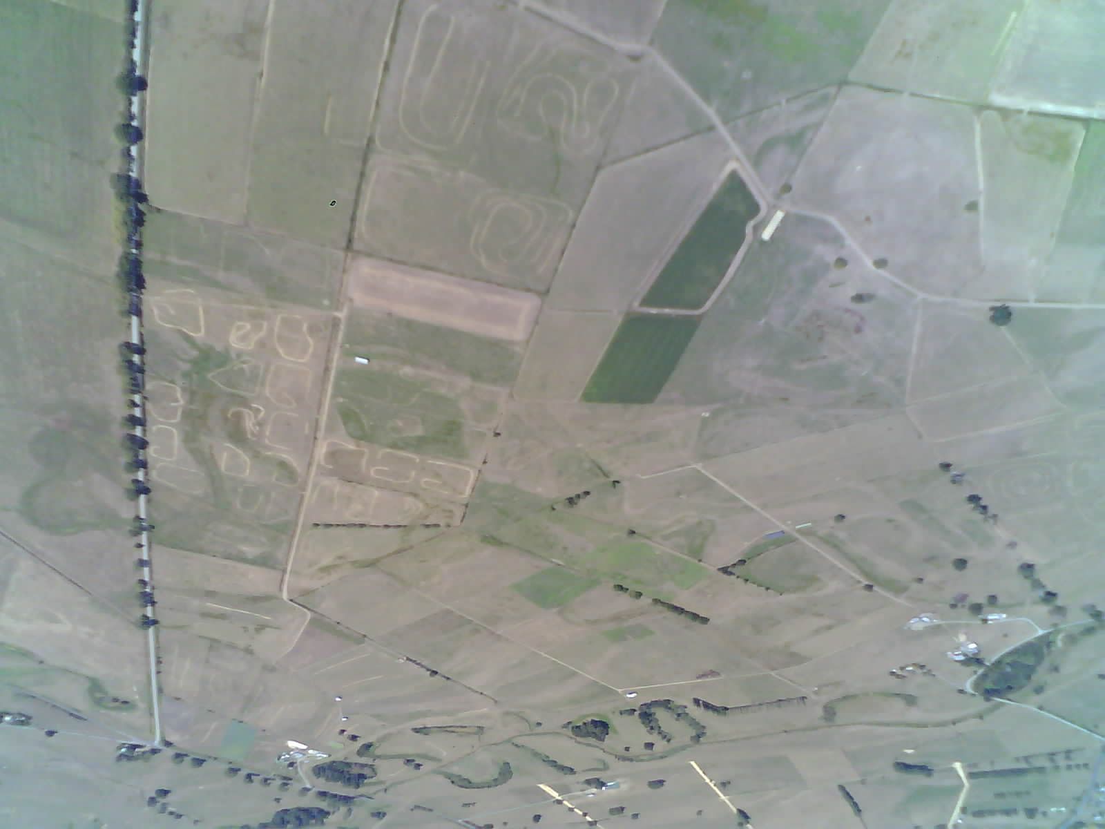
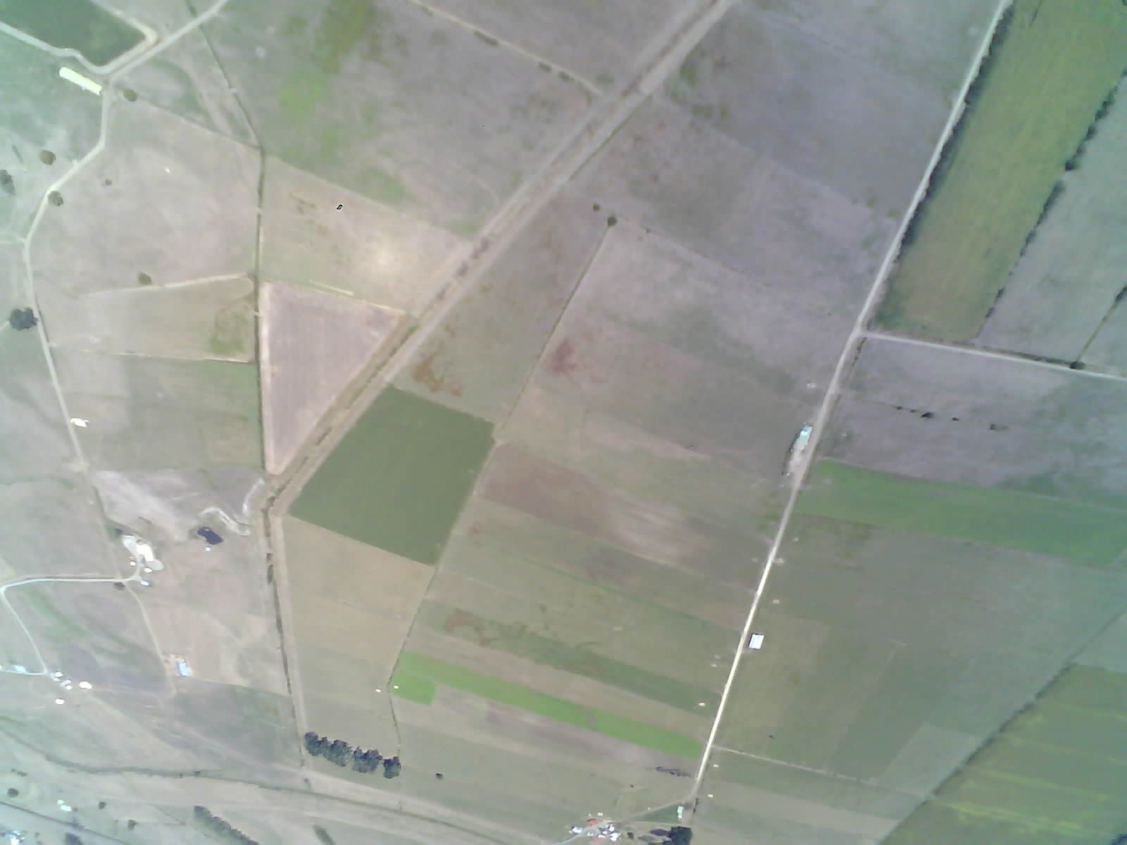
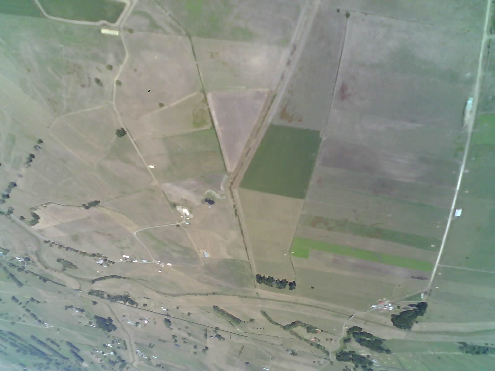
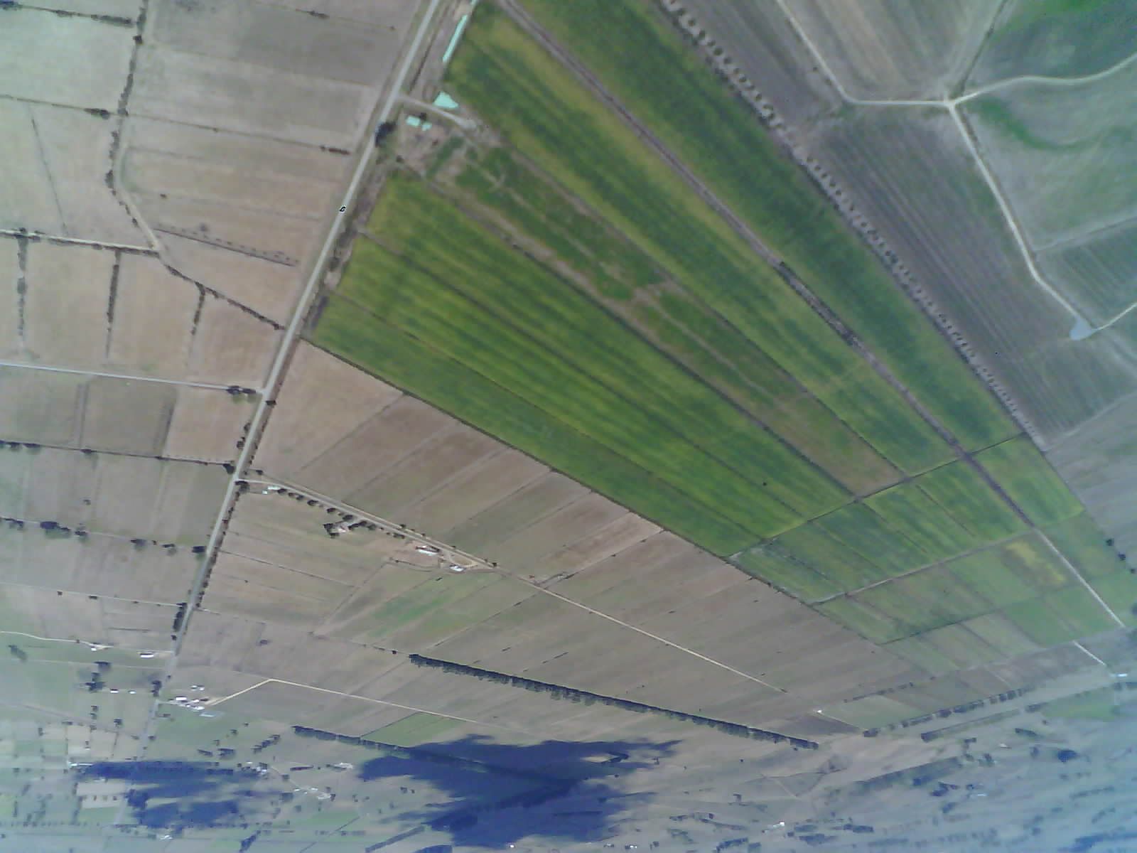
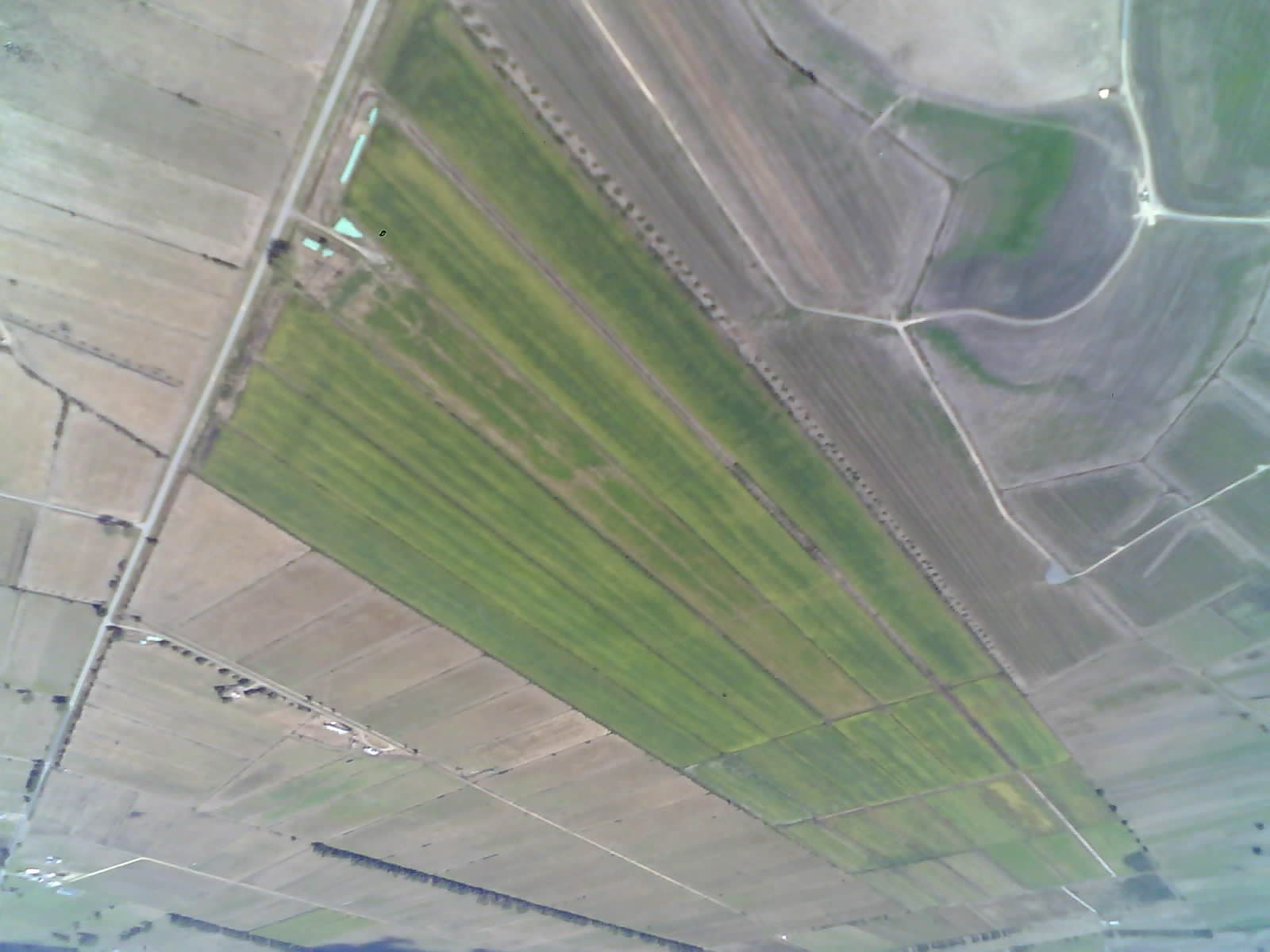
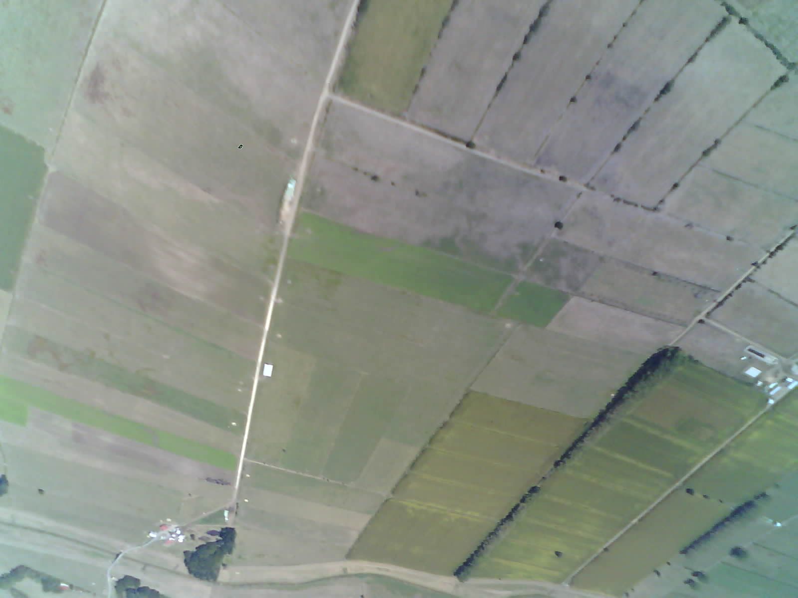
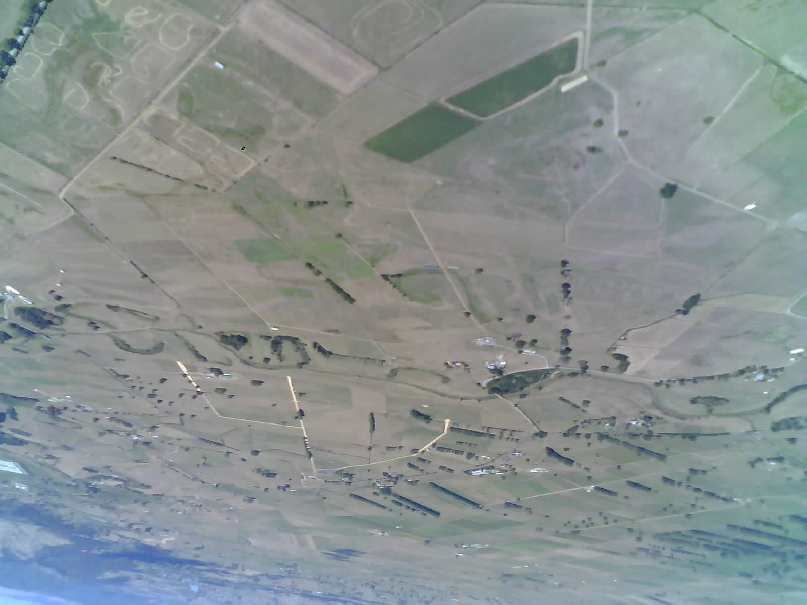
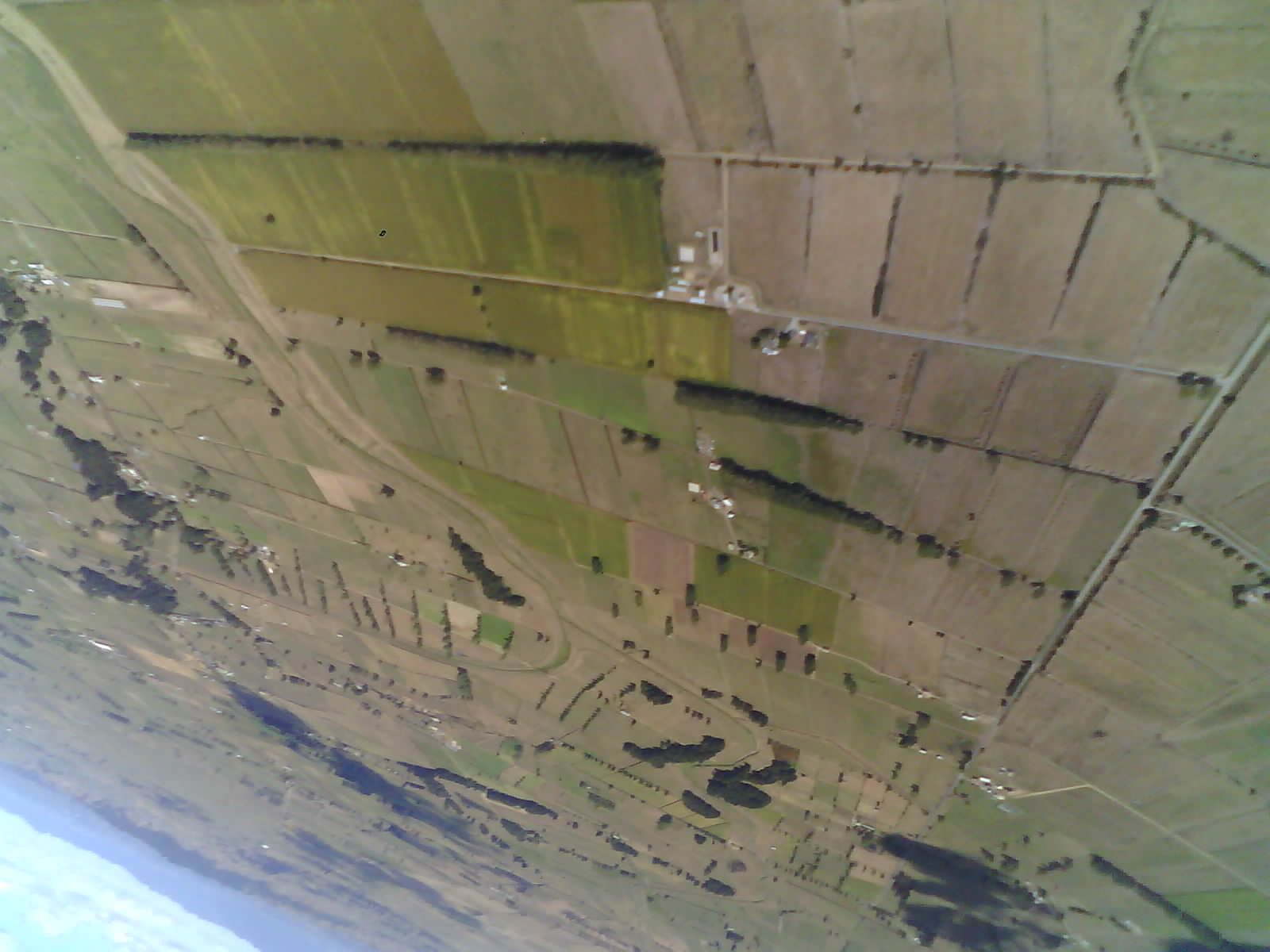
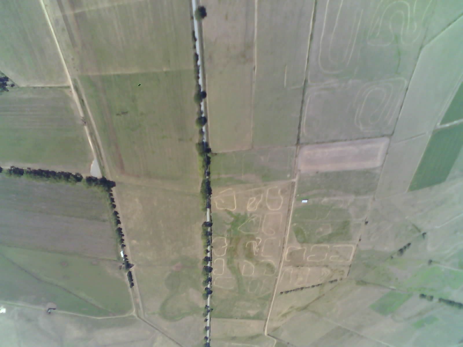
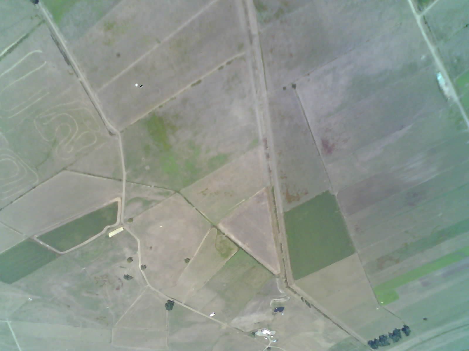
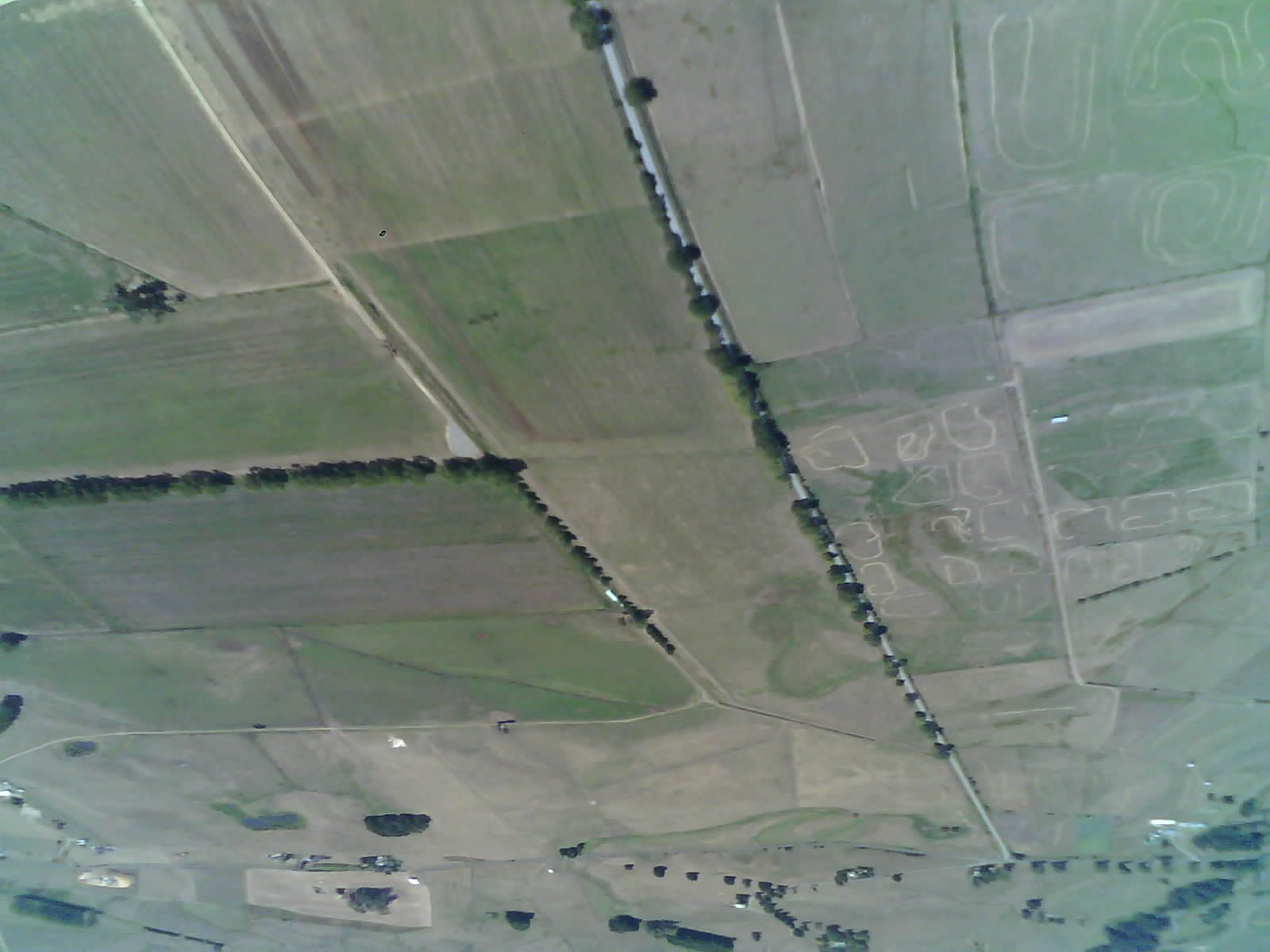
Here’s the first non blank photo (first), along with the satellite imagery of the location (second), so you can see the speed for yourself.